
Owner's manual

FT 5000 EVB Hardware Guide 17
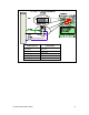
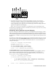
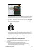
The following table lists the IO pins and IO devices associated with the jumpers on JP32.
Jumper I/O Pin IO Device/Functionality on FT 5000 EVB
1-2 IO6 SWSH (Shift register latch strobe for SW2 and Joystick)
3-4 IO7 TEMP (temperature sensor)
5-6 IO8 RXUSB (USB receive)
7-8 IO9 SW1
9-10 IO10 TXUSB (USB transmit)
11-12 IO3 PD (connects a 499 Ω pull-down resistor to IO3)
13-14 IO1 PD (connects a 499 Ω pull-down resistor to IO1)
15-16 IO9 PD (connects a 499 Ω pull-down resistor to IO9)
Connecting the USB Interface
You can enable serial communication without handshake lines and then connect your FT 5000 EVB to
your development computer via a USB interface. This lets you perform application-level debugging,
tests, or diagnosis. Once you create this USB connection, you can output debugging and tracing
information from the device application running on your FT 5000 EVB to a terminal emulation
program on your computer such as Windows HyperTerminal.
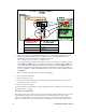
To create the USB connection for performing application-level debugging, follow these steps:
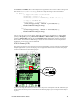
1. Connect the type A connector on a USB Type A to Type B Cable to an available USB port on
your computer, and then connect the type B connector to the USB interface on the left side of the
FT 5000 EVB.
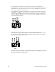
2. Connect jumpers 5-6 (IO8 RXUSB) and 9-10 (IO10 TXUSB) on JP32. This connects the IO8 and
IO10 pins on the FT 5000 Smart Transceiver to the USB communications interface on the board.
IO10 is connected to pin 5 RXD as a serial data output to the USB interface, and IO8 is connected
to pin 1 TXD as a serial data input from the USB interface.