FT 5000 EVB Hardware Guide ® 078-0390-01B
Echelon, LON, LonWorks, Neuron, 3120, 3150, Digital Home, i.LON, LNS, LonMaker, LonMark, LonPoint, LonTalk, NodeBuilder, ShortStack, and the Echelon logo are trademarks of Echelon Corporation registered in the United States and other countries. FTXL, LonScanner, LonSupport, ISI, OpenLDV, and LNS Powered by Echelon are trademarks of Echelon Corporation. Other brand and product names are trademarks or registered trademarks of their respective holders.
Table of Contents Preface ........................................................................................................... iv Welcome.......................................................................................................... v Purpose ........................................................................................................... v Audience.......................................................................................................... v Box Contents ...........
Preface The FT 5000 EVB is a development board for evaluating the LONWORKS 2.0 platform and creating LONWORKS devices. The FT 5000 EVB is a complete Series 5000 LONWORKS device that uses an FT 5000 Smart Transceiver. It includes a variety of I/O devices that you can use to develop prototype and production devices.
Welcome The FT 5000 EVB is a complete Series 5000 LONWORKS device that you can use to evaluate the LONWORKS 2.0 platform and create LONWORKS devices. The FT 5000 EVB includes a FT 5000 Smart Transceiver with an external 10 MHz crystal (you can adjust the system’s internal clock speed from 5MHz to 80MHz), an FT-X3 communication transformer, 64KB external serial EEPROM and flash memory devices, and a 3.3V power source.
• Quick Start Guide. The FT 5000 EVB hardware is shipped with either a NodeBuilder FX or Mini FX Quick Start Guide. This document describes how to install the software included with your FT 5000 EVB; connect the FT 5000 EVBs and your development computer to a LONWORKS FT-10 channel; and create a simple LONWORKS network using the Neuron C example application pre-loaded on the FT 5000 EVB. • Power supplies (90–240VAC 50/60Hz) with power cords (US/Japan and Continental European).
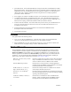
Mini FX User’s Guide Describes how to use the Mini FX Application to develop a prototype or production control system that requires networking, particularly in the rapidly growing, price-sensitive mass markets of smart light switches, thermostats, and other simple devices and sensors. Neuron® C Reference Guide Provides reference information for writing programs using the Neuron C language.
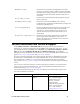
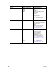
viii Region Europe Languages Supported English German French Italian Contact Information Echelon Europe Ltd. Suite 12 Building 6 Croxley Green Business Park Hatters Lane Watford Hertfordshire WD18 8YH United Kingdom Phone: +44 (0)1923 430200 Fax: +44 (0)1923 430300 lonsupport@echelon.co.uk Japan Japanese Echelon Japan Holland Hills Mori Tower, 18F 5-11-2 Toranomon, Minato-ku Tokyo 105-0001 Japan Phone: +81-3-5733-3320 Fax: +81-3-5733-3321 lonsupport@echelon.co.
1 Connecting the FT 5000 EVB Hardware This chapter describes how to power your FT 5000 EVB and connect it to a LONWORKS FT-10 channel and to your development computer. . .
Connection Instructions To connect the FT 5000 EVB boards, follow these steps: 1. Unpack the equipment from the shipping carton. Note: The FT 5000 EVB boards are shipped in protective anti-static packaging. When assembling the FT 5000 EVB boards, the boards must not be subjected to high electrostatic potentials. Avoid touching the component pins, or any other metallic equipment on the evaluation boards. 2. Verify that all of the following hardware and software items are present. Item 3. 4.
5. Connect one of the orange network connectors on each FT 5000 EVB to the included network cable. Each board contains two orange network connectors (JP101, JP102) that are connected together. You can use these network connectors to daisy-chain multiple devices. 6. Use the included U10 USB Network Interface to attach your development computer to the TP/FT-10 channel.
If this is the only LONWORKS interface installed on your computer, it will automatically use the default name LON1, and you can proceed directly to your software application and begin using the interface as LON1. If you have another network interface installed on your computer, you can check the name used by the U10 USB Network Interface in the LONWORKS Interfaces application. You can also use this application to configure the buffer sizes and counts used by the U10 USB Network Interface.
2 FT 5000 EVB Hardware Details This chapter describes the Neuron core, service pin and reset buttons and LEDs, I/O devices, and jumper settings on the FT 5000 EVB hardware.
Introduction to FT 5000 EVB Hardware Details The following sections provide additional details on the FT 5000 EVB hardware, including descriptions of the core circuit, I/O devices, service and reset buttons and LEDs, and jumper settings. You can view schematics for the peripheral circuitry of the FT 5000 EVB. The peripheral circuitry is the section of the evaluation board external to the core circuit that is labeled CORE.
I/O Devices This section briefly describes the I/O devices included on the FT 5000 EVB, which consists of two push buttons, two LEDs, a temperature sensor, a light sensor, an LCD, and a joystick. Push Button Switches The FT 5000 EVB includes two push-button switches. The switches are labeled SW1 and SW2. The SW1 push button is connected to the IO9 pin on the FT 5000 Smart Transceiver.
LCD The FT 5000 EVB includes a 4 x 20 character LCD with a yellow-green backlight from Newhaven Display International Inc (Part No. NHD-0420D3Z-FL-GBW). The LCD is connected to the FT 5000 Smart Transceiver IO0 and IO1 pins (via the I2C interface). For more information about this LCD, see its data book at www.newhavendisplay.com/specs/NHD-0420D3Z-FL-GBW.pdf. Joystick The FT 5000 EVB includes a 4-way joystick with center push button from ALPS® Electric Co (Part No. SKQUCAA010).
Jumper Settings The FT 5000 EVB contains multiple sets of jumpers that you can use to configure the board. The following sections display the locations of the jumpers on the FT 5000 EVB, show the default settings of the jumpers, and describe how to use the jumpers to enable and disable various connections on the board.
3. Press the Reset button. 4. Re-connect the jumpers. 5. Reload the rebuilt application image file for the device running on the FT 5000 EVB. Flash ICE Connection (JP23) This header can be used to connect a SPI interface flash ICE, which you can use instead of the external serial non-volatile memory flash device on the FT 5000 EVB.
Performing In-Circuit Programming of External Serial Memory Devices The JP23 header along with the jumpers on JP1 provides support for third-party in-circuit device programmers, which you can use to update the data in the external serial EEPROM and flash devices used by the FT 5000 Smart Transceiver on the FT 5000 EVB. This provides an alternative to loading application images into these external serial memory devices over the TP/FT-10 network.
5. Connect your external serial EEPROM or flash memory device to a compatible device programmer. Echelon has tested the Aardvark™ I2C/SPI USB Host Adapter from TotalPhase™ (Part No. TP240141), with the 10-pin split cable from TotalPhase (Part No. TP240212), as one method for creating this connection (for more information on this adapter, go to the TotalPhase Web site at www.totalphase.com/products/aardvark_i2cspi/).
Aardvark Programmer Lead Connector FT 5000 EVB SPI Interface (Serial Flash) SS (White) JP1, pin 2 MISO (Green) SCK (Purple) JP23, pin 3 JP23, pin 6 GND (Black) JP23, pin 7 MOSI (Grey) JP23, pin 8 FT 5000 EVB Hardware Guide 13
Aardvark Programmer Lead Connector SCL (Brown) 6. FT 5000 EVB I2C Interface (Serial EEPROM) SDA (Orange) JP1, pin 8 JP1, pin 6 GND (Red) JP23, pin 7 Program your external serial EEPROM or flash memory device using an application such as the Flash Center Memory Programmer from TotalPhase. You can download the Flash Center Memory Programmer for free from the TotalPhase Web site at www.totalphase.com/products/flash_center/#downloads.
chapter for more information about the Gizmo header). By default, this header is open as illustrated in the following figure: LCD, Light Sensor, LEDs, Switch, and Joystick Connections (JP31) This set of jumpers is used to connect the LCD, Light Sensor, LEDs, and the shift register for the SW2 push button (lines 1 and 2 of three) and joystick (SW3) on the FT 5000 EVB. The 13-14 and 15-16 pins on JP31 are used with the 1-2 pins on JP32 for bitshift I/O with the SW2 push button and the Joystick.
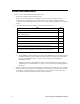
The following table lists the I/O pins and I/O devices associated with the jumpers on JP31.
The following table lists the IO pins and IO devices associated with the jumpers on JP32.
3. Run Windows HyperTerminal or another terminal emulation program on your computer to monitor the serial output. Configure your terminal emulation program for direct connection to your serial port using the serial parameters specified in the device application. See the next section, Configuring a Device Application for Serial Debugging, for how to configure your device application for application-level debugging. Note: You can use only one of the EIA-232 or USB interfaces on the FT 5000 EVB at a time.
The Switch.nc and LED.nc files in the example device applications store various values in strings and then call the EvalBoardPrintDebug()function to output the strings to the serial interface. if (bOn) { // Toggle the state of the switch nvoSwitch[0].state ^= 1; nvoSwitch[0].value = nvoSwitch[0].
EIA-232 Interface (JP201and JP203) This set of jumpers enables the EIA-232 and ShortStack interfaces on the FT 5000 EVB. These jumpers are disconnected by default (these interface are disabled) as illustrated in the following figure: You can enable the EIA-232 interface without and with handshake lines. You can enable the EIA-232 interface without handshake lines to connect your FT 5000 EVB to your development computer for performing application-level debugging.
2. Verify that jumpers 5-6 (RXUSB) and 9-10 (TXUSB) on JP32 for the USB interface are disconnected. This is because you can only use one of the EIA-232 and USB interfaces on the FT 5000 EVB at a time. See Switch, Temperature Sensor, Joystick, and USB Connections (JP32) earlier in this chapter for more information. 3. Connect jumpers 1-2 (IO8 R10) and 7-8 (IO10 T1IN) on JP201. This connects the IO8 and IO10 pins on the FT 5000 Smart Transceiver to the EIA-232 communications interface on the board.
22 2. Verify that jumpers 5-6 (RXUSB) and 9-10 (TXUSB) on JP32 for the USB interface are disconnected. This is because you can only use one of the EIA-232 and USB interfaces on the FT 5000 EVB at a time. See Switch, Temperature Sensor, Joystick, and USB Connections (JP32) earlier in this chapter for more information. 3. Connect jumpers 1-2 (IO8 R10), 3-4 (IO4 R20), and 7-8 (IO10 T1IN) on JP201.
6. If you are using the EIA-232 interface to connect your FT 5000 EVB to ShortStack host processor, or if you planning to connect a microcontroller via an SCI connection but without the EIA-232 level shifter, see Connecting the ShortStack Interface for more information on how to do this. Connecting the ShortStack Interface You can use JP201, JP203, JP24 and JP32 jumpers to control connections to a micro controller, such as a ShortStack host processor, without or without the EIA-232 level shifter.
24 FT 5000 EVB Hardware Details
Gizmo 5V or 3.3V Power Select (JP204) This jumper connects 5V or 3.3V power to the Gizmo connector (P201, pin 19) on the FT 5000 EVB. You can use the Gizmo connector for the external use of the 12 I/O pins of the FT 5000 Smart Transceiver and the power supply (5V or 3.3V). The 5V and 3.
To connect 3.3V power to the 3V pin on the Gizmo connector (P201, pin 17), connect the shunt between pins 1 and 2 as demonstrated in the following figure: I/O Connector The following figure shows the I/O connector pinout for the FT 5000 EVB board. You can use this connector to attach custom I/O devices to an evaluation board.
Design and Test for Electromagnetic Compatibility Echelon’s free topology twisted pair technologies support the creation of products that meet a wide variety of regulatory requirements. Chapter 4 of the FT 5000 Smart Transceiver Data Book describes how to create products with Echelon’s free topology twisted pair technology that meet electromagnetic compatibility regulations. The FT 5000 EVB boards are designed to facilitate testing of Echelon’s free topology twisted pair technologies.
www.echelon.