
User guide

Chapter 3 - Input/Output Interfaces
90 FT 3120 / FT 3150 Smart Transceiver Data Book
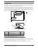
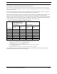
Table 3.7 Timer/Counter Square Wave Output
This table is for 10MHz input clock. Scale appropriately for other clock rates:
Period (µs) = 512 x 2
Clock Select
/ (Input Clock in MHz)
Frequency (Hz) = 1,000,000 / Period (µs).
For 20MHz and 40MHz operation, the numbers should be scaled accordingly.
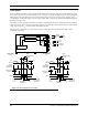
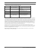
For pulsewidth long output, Table 3.8 gives the possible choices for pulsetrain repetition frequencies.
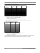
Table 3.8 Timer/Counter Pulsetrain Output
This table is for 10MHz input clock. Scale appropriately for other clock rates:
Period (ms) = 131.072 x 2
Clock Select
/ (Input Clock in MHz)
Frequency (Hz) = 1,000 / Period (ms)
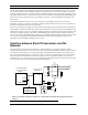
As with all CMOS devices, floating I/O pins can cause excessive current consumption. To avoid this, declare all
unused I/O pins as bit output. Alternatively, unused I/O pins may be connected to + V
DD
or GND.
Clock Select
(System Clock ÷)
Repetition Rate
(Hz)
Repetition
Period
(µs)
Resolution
of Pulse
(µs)
0 (÷1) (5MHz) 19,531 51.2 0.2
1 (÷ 2) (2.5MHz) 9,766 102.4 0.4
2 (÷ 4) (1.25MHz) 4,883 204.8 0.8
3 (÷ 8) (625 kHz) 2,441 409.6 1.6
4 (÷ 16) (312.5 kHz) 1,221 819.2 3.2
5 (÷ 32) (156.25 kHz) 610 1,638.4 6.4
6 (÷ 64) (78.125 kHz) 305 3,276.8 12.8
7 (÷ 128) (39.06 kHz) 153 6,553.6 25.6
Clock Select
Frequency
(Hz)
Period
(ms)
0 76.3 13.1
1 38.1 26.2
2 19.1 52.4
3 9.54 105
4 4.77 210
5 2.38 419
6 1.19 839
7 0.60 1,678