
User guide

FT 3120 / FT 3150 Smart Transceiver Data Book 61
Serial I/O Objects
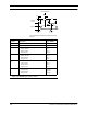
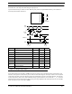
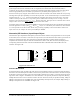
LSB first. In addition, any one of the pins IO0 – IO7 may be used as a timeout pin to prevent lockup in case of
abnormal abort of the input bit stream during the input process.
Up to 40 characters may be read at one time. Both the parity and the Longitudinal Redundancy Check (LRC) are
checked by the FT Smart Transceiver.
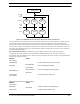
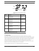
Figure 3.26 Magcard Input Object
A FT Smart Transceiver operating at 10MHz can process a bit rate at up to 8334 bits/second (of a bit density of 75
bits/inch). This equates to a card velocity of 111 inches/second. Most magnetic card stripes contain a 15-bit sequence
of zero data at the start of the card, allowing time for the application to start the card reading function. At 8334 bits/
second, this period is about 1.8 ms. If the scheduler latency is greater than the 1.8 ms value, the io_in() function
will miss the front end of the data stream. The bit rate processing capability scales with input clock rate. For example:
the bit rate may be up to 33,336 bps at 40MHz.
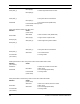
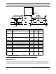
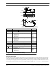
Symbol Description Min Typ Max
t
fin
Function call to first clock input — 45.0 µs —
t
hold
Data hold 0 µs — —
t
setup
Data setup 0 µs — —
t
low
Clock low width 60 µs — —
t
high
Clock high width 60 µs — —
t
wto
Width of timeout pulse 60 µs — —
t
clk
Clock period 120 µs — —
t
tret
Return from timeout 21.6 µs — 81.6 µs
t
ret
Return from function — — 301.8 µs
t
setup
t
tret
Serial Data
Clock
IO10
IO9
IO8
IO0
IO1
IO2
IO3
IO4
IO5
IO6
IO7
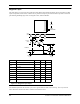
CLOCK
(IO8)
TIMEOUT
DATA
(IO9)
TIME
t
ret
START OF
io_in()
END OF
io_in()
t
wto
Timeout
t
fin
t
low
t
clk
t
hold
t
high