
User guide


Chapter 3 - Input/Output Interfaces
46 FT 3120 / FT 3150 Smart Transceiver Data Book
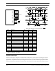
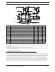
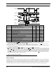
Figure 3.15 Muxbus I/O Object
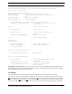
Parallel Input/Output
Pins IO0 – IO10 may be configured as a bidirectional 8-bit data and 3-bit control port for connecting to an external
processor. The other processor may be a computer, microcontroller, or another FT Smart Transceiver (for gateway
applications). The parallel interface may be configured in master, slave A, or slave B mode. Typically, two FT Smart
Transceivers interface in master/slave A mode and a FT Smart Transceiver
interfaces with another microprocessor in
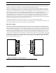
Symbol Description Min Typ Max
t
fout
io_out() to valid address — 26.4 µs —
t
as
Address valid to address strobe — 10.8 µs —
t
ahw
Address hold for write — 4.8 µs —
t
ahr
Address hold for read — 6.6 µs —
t
was
Address strobe width — 6.6 µs —
t
wrs
Read strobe width — 10.8 µs —
t
wws
Write strobe width — 10.8 µs —
t
dws
Data valid to write strobe — 6.6 µs —
t
rset
Read setup time 10.8 µs — —
t
whold
Write hold time 4.2 µs — —
t
rhold
Read hold time 0 µs — —
t
adrs
Address disable to read strobe — 7.2 µs —
t
fin
io_in() to valid address — 26.4 µs —
t
rret
Function return from read — 4.2 µs —
t
wret
Function return from write — 4.2 µs —
t
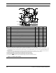
rret
C_WS
C_ALS
C_ALS
(IO8)
C_RS
(IO10)
ADDR/
DATA
TIME
START OF
io_out()
END OF
io_in()
t
fout
t
ahw
t
as
C_RS
ADDR
DATA
ADDR
DATA
t
as
t
ahr
t
adrs
t
dws
t
wrs
t
rhold
t
rset
C_WS
(IO9)
START OF
io_in()
END OF
io_out()
t
wws
t
fin
t
wret
IO10
IO9
IO8
IO0
IO1
IO2
IO3
IO4
IO5
IO6
IO7
AD0 – AD7
t
whold
t
was
NOTE: Data is latched 4.8 µs after the falling edge of C_RS.