
User guide

FT 3120 / FT 3150 Smart Transceiver Data Book 35
Hardware Considerations
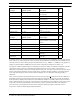
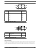
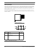
Table 3.4 Summary of Timer/Counter Input Objects
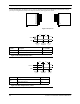
Table 3.5 Summary of Timer/Counter Output Objects
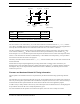
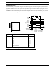
To maintain and provide consistent behavior for external events and to prevent metastability, all 11 I/O pins of the FT
Smart Transceiver, when configured as inputs, are passed through a hardware synchronization block sampled by the
internal system clock. This is always the input clock divided by two (e.g. 10MHz ÷ 2 = 5MHz). For any signal to be
reliably synchronized with a 10MHz input clock, it must be at least 220 ns in duration (see Figure 3.2).
All inputs are software sampled during when statement processing. The latency in sampling is dependent on the I/O
object which is being executed (see I/O timing specification and Neuron C Programmer’s Guide for more
information). These latency values scale inversely with the input clock. Thus, any event that lasts longer than 220 ns
will be synchronized by hardware, but there will be latency in software sampling resulting in a delay detecting the
event. If the state changes at a faster rate than software sampling can occur, then the interim changes will go
undetected.
There are two exceptions to the synchronization block. First, the chip select (CS
) input used in the slave B mode of
the parallel I/O object; this input will recognize rising edges asynchronously (see page 45). Second, the leveldetect
input is latched by a flip flop with a 200ns clock. The leveldetect transition event will be latched, but there will be a
delay in software detection (see page 43). The input timer/counter functions are also different, in that events on the I/
O pins will be accurately measured and a value returned to a register, regardless of the state of the application
processor. However, the application processor may be delayed in reading the register. Consult the Neuron C
Programmer’s Guide for detailed programming information.
I/O Object Applicable I/O Pins Input Signal
Page
No.
Dualslope Input IO0, IO1 + (one of IO4 – IO7) Comparator output of the dualslope
converter logic
71
Edgelog Input IO4 A stream of input transitions 72
Infrared Input IO4 – IO7 Encoded data stream from an infra-
red demodulator
73
Ontime Input IO4 – IO7 Pulse width of 0.2 µs – 1.678 s 74
Period Input IO4 – IO7 Signal period of 0.2 µs – 1.678 s 75
Pulsecount Input IO4 – IO7 0 – 65,535 input edges during 0.839
s
77
Quadrature Input IO4 + IO5, IO6 + IO7 ± 16,383 binary Gray code transi-
tions
78
Totalcount Input IO4 – IO7 0 – 65,535 input edges 79
I/O Object Applicable I/O Pins Output Signal
Page
No.
Edgedivide Output IO0, IO1 + (one of IO4 – IO7) Output frequency is the input fre-
quency divided by a user-specified
number
80
Frequency Output IO0, IO1 Square wave of 0.3 Hz to 2.5MHz 81
Oneshot Output IO0, IO1 Pulse of duration 0.2 µs to 1.678 s 83
Pulsecount Output IO0, IO1 0 – 65,535 pulses 84
Pulsewidth Output IO0, IO1 0 – 100% duty cycle pulse train 85
Triac Output IO0, IO1 + (one of IO4 – IO7) Delay of output pulse with respect to
input edge
86
Triggered-
count Output
IO0, IO1 + (one of IO4 – IO7) Output pulse controlled by counting
input edges
87