
User guide

FT 3120 / FT 3150 Smart Transceiver Data Book 25
Additional Functions
• State wait — wait for the device to leave the applicationless state.
• Pointer initialization — perform a global pointer initialization.
• Initialization step — execute initialization task, which is created by the compiler/linker to handle initializa-
tion of static variables and the timer/counters.
• I/O pin initialization step — initialize I/O pins based on application definition. Prior to this point, I/O pins
are high impedance.
• State wait II — wait for the device to leave the unconfigured or hard-offline state. If waiting was required, a
flag is set to indicate that the device should come up offline.
• Parallel I/O synchronization — devices using parallel I/O attempt to execute the master/slave synchroni-
zation protocol at this point.
• Reset task — execute the application reset task (when (reset{})).
If the offline flag was set, go offline and execute the offline task. If the BIST flag indicated a failure, then the
SERVICE
pin is turned on and the offline task is executed. Otherwise, the scheduler starts its normal task scheduling
loop.
The amount of time required to perform these steps depends on many factors, including: FT Smart Transceiver
model; input clock rate; whether or not the device performs a boot process; whether the device is applicationless,
configured, or unconfigured; amount of off-chip RAM; whether the off-chip RAM is tested or simply cleared; the
number of buffers allocated; and application initialization. Table 2.8 and Table 2.9 summarize the number of input
clock cycles (CLK1) required for each of these steps for the FT 3120 and the FT 3150 Smart Transceivers. The times
are approximate and are given as functions of the most significant application variables.
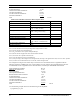
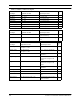
Table 2.8 FT 3120 Smart Transceiver Reset Sequence Time
Notes:
Note 1) These tasks run in parallel with other tasks.
Note 2) B is the number of application and/or network buffers allocated.
Note 3) M is the number of bytes to be checksummed.
Note 4) Assumes a trivial initialization task, no reset task and the configured state.
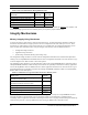
For example, the timing of each of these steps is shown for a FT 3120 Smart Transceiver application with the
following parameters: 10MHz input clock, crystal oscillator, no boot required, at least 10 application and/or network
buffers, and 500 bytes of EEPROM checksummed.
Stack Initialization and BIST 38.6 ms
SERVICE
Pin Initialization 0.1 ms
State Initialization 0.025 ms
Off-Chip RAM Initialization 0 ms
Random Number Seed Calculation 0 ms
Step Number of CLK1 Cycles Notes
Stack Initialization and BIST 386,000
SERVICE Pin Initialization 1000
State Initialization 250 (for no boot)
2,275,000 (for boot)
Off-Chip RAM Initialization 0
Random Number Seed Calculation 0 1
System RAM Set-up 21,000 + 600*B 2
Communication Port Initialization 0 1
Checksum Initialization 3400 + 175*M 3
One-Second Timer Initialization 6100
Scheduler Initialization ≥ 7400 4