
User guide

FT 3120 / FT 3150 Smart Transceiver Data Book 113
Cable Termination and Shield Grounding
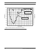
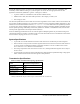
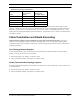
Table 5.2 Free Topology Specifications
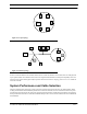
The free topology transmission specification includes two components that must both be met for proper system
operation. The distance from each transceiver to all other transceivers and to the termination (including the LPI-10
termination, if used) must not exceed the maximum device-to-device distance. If multiple paths exist, e.g., a loop
topology, then the longest path should be used for calculations. The maximum total wire length is the total length of
wire within a segment.
Cable Termination and Shield Grounding
TP/FT-10 network segments require termination for proper data transmission performance. The type of
terminator varies depending on whether shielded or unshielded cable is used. Free topology and Bus topology
networks also differ in their termination requirements. The following sections describe the various terminators and
termination procedures.
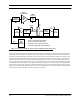
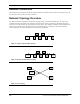
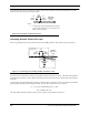
Free Topology Network Segment
In a free topology segment, only one termination is required and may be placed anywhere on the free topology
segment. There are two choices for the termination:
1. RC network (Figure 5.6), with Ra = 52.3 ±1%, 1/8W
2. LPI-10 Link Power Interface, with jumper at “1 CPLR” setting.
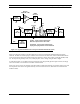
Doubly Terminated Bus Topology Segment
In a doubly terminated bus topology, two terminations are required, one at each end of the bus. There are two choices
for each termination:
3. RC network (Figure 5.6), with Ra = 105 ±1%, 1/8W
4. LPI-10 Link Power Interface, with jumper at “2 CPLR” setting.
Cable
Maximum
device-to-device
distance
Maximum total
Wire length (Meters)
Belden 85102 500 500
Belden 8471 400 500
Level IV, 22AWG 400 500
JY(St) Y 2x2x0.8 320 500
TIA Category 5 250 450
Ω
Ω