
User's Manual


78 MEP Devices
MEP Interface
The ANSI v3.1 meter (83011-83301) optionally provides a new bi-directional, isolated
UART serial port that is called a MEP port. The MEP port allows a connected smart
device to access meter data, run meter procedures, and have limited write access to
the meter.
The device that connects to the meter using the MEP port is referred to as a MEP
device. The MEP device is controlled and accessed through NES in largely the same
way as an M-Bus device is. However, there are several fundamental differences
between a MEP device and an M-Bus device, most notably in the way a MEP device
interacts with an Echelon electric meter – the MEP device initiates communication
with the meter and can access meter tables and procedures. A separate document,
the MEP Device Developer’s Guide, provides an introduction to the MEP protocol and
describes the MEP interface, including definitions of the meter tables and procedures
you will use when programming your MEP device.
There are many different tasks you could accomplish with a MEP device. For
example, you could connect a smart RF card that communicates with In Home
Display devices that that would reflect the current state of the meter, as the MEP
device is able to read meter data in real-time. Alternatively, you could connect an
auxiliary I/O device meant to deliver external alarm signals to the meter using the
MEP port.
The MEP port can optionally supply power to a low-powered MEP device. When you
order your meter, you can specify whether you want the powered or the unpowered
MEP option. MEP devices could reside under the terminal cover of an ANSI meter,
although MEP applications with other mechanical or power constraints should be
developed as external devices to the meter. The MEP port is accessible via the
meter’s auxiliary terminals. The meter terminals for the MEP interface are listed
below. For more information on the MEP interface and MEP devices, including
hardware details and an overview of the MEP protocol, consult the MEP Device
Developer’s Guide.
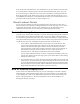
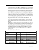
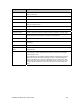
Electrical Specification
External MEP Interface
Meter
Terminal
Name MEP
Direction
Function Comments
14 M-Bus(+) O M-Bus Power 4kV isolated M-Bus port (+)*
(+12Vdc/+24Vdc)
15 M-Bus(-) I/O M-Bus Data 4kV isolated M-Bus port (-)*
16 MEP_PWR O MEP POWER +24Vdc nominal *
16A MEP_COM_TXD O MEP TXD Meter’s Transmit
17 MEP_COM_RXD I MEP RXD Meter’s Receive
18 MEP_COM_ENABLE I MEP COM
ENABLE
MEP +12V/+5V Interface Enable
19 MEP_COM_GND - MEP GND MEP GND Interface Power