
User's Manual

CRD 3000 Integrator’s Guide
19
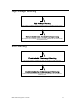
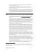
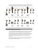
Note that the Segment Controller does not share a power line connection with the
luminaires on the other side of the RF bridge; the CRD 3000 Street Light Bridge
modules forward all communications between the two network segments.
Figure 5. Basic Street Light Bridge Installation (Typical US Installation)
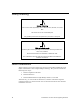
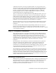
Figure 6. Basic Street Light Bridge Installation (Typical European Installation)
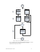
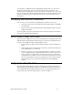
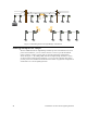
Extending a Basic Installation
A single CRD 3000 Street Light Bridge module can communicate with more than
one companion CRD 3000 Street Light Bridge module to define a more complex
configuration. Figure 7 shows an extension to the configuration shown in
Figure 5 (a European installation is not shown, but can be extended in the same
way). A single CRD 3000 Street Light Bridge module communicates with three
CRD 3000 Street Light Bridge modules to further extend the range of the
Segment Controller and provide communications to a greater number of
luminaires.
Communications between the Segment Controller and the network segments in
the foreground (the bottom of Figure 7) connect to the Segment Controller’s
network segment through an RF hop.