
Installation Guide
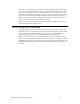
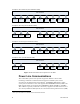
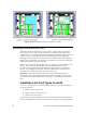
Table Of Contents
- Welcome
- Audience
- Related Documentation
- FCC Notice
- RF Statements
- EMC and Safety Statements
- 1. Introduction
- 2. Installing Components and Troubleshooting
- 3. Pole Mount Installation
- 4. Pad Mount Installation
- Introduction
- Required Tools
- Installation Location
- Preparing the Transformer Pad
- Preparing for Installation
- Performing the Installation
- Extend Pad Mounting Bracket
- Attach Pad Mounting Bracket to Lifting Nut
- Attach Conduit Housing to Pad Mounting Bracket
- Insert Conduit Thread into Conduit Housing
- Attach ECN to Pad Mounting Bracket
- Secure ECN to Pad Mounting Bracket
- Connect the ECN to Power and the Network
- Close and Lock the Conduit Housing
- Complete the Installation
- Verifying Successful Installation
- 5. Field Replacement for an ECN 7000 Series Device
- A. ECN 7000 Series Specifications
- B. Safety and High-Voltage Warnings
- C. ESD and Battery Warnings
16 Introduction
The ECN external connection panel includes two 8 Position 8 Contact (8P8C; also
known as RJ45) modular connectors for connecting to the Ethernet network. You
can use standard ANSI/TIA/EIA-568-A Category 5 cable in either the T568A or
T568B wiring configuration. These Ethernet connectors have built-in
transformers on the ECN main system board.
The external connector is included with the External Connections + Serial option.
Wi-Fi
The ECN can include a Wi-Fi access point that supports simultaneous dual-band
Wi-Fi clients.
An option is also available that supports the draft IEEE 802.11s Wi-Fi meshing
standard.
EV-DO
The ECN can include an Evolution-Data Optimized (EV-DO) modem that
conforms to the TIA-856 Rev. B standard. For US models, the modem has been
certified through the Verizon Wireless™ Open Development program to operate
with the Verizon Wireless 3G network. Thus, the ECN can provide broadband
Internet access to devices at the edge of the Smart Grid.
USB
The ECN main system board includes two Universal Serial Bus (USB) host
controllers. These hosts allow connectivity to the three USB hubs that are
included on the ECN main processor system card and to the six expansion slots.
The USB hosts support the USB 1.1 specification at either 1.5 Mbit/s (Low-
Bandwidth) or 12 Mbit/s (Full-Bandwidth).
All expansion slots support a USB power interconnect (+1.8 VDC to +12 VDC
variable-voltage input determined by the expansion card) and USB data
interconnect.
Serial
The ECN can include serial communications connectors that provide serial ports
for communicating with serial devices. The serial ports use standard 5-wire EIA-
232 interface with a standard 9-pin female DE-9 connectors.
There is also an optional Distributed Network Protocol (DNP3) driver available
for process automation and distribution automation systems.
The serial connections are included with the External Connections + Serial
option.
Multi-Utility Meters
The ECN expansion slots support several wired and wireless technologies that
allow the ECN to monitor advanced multi-utility meters, such as water and gas
meters. Thus, the ECN can gather information about many forms of energy and
power being used at the edge of the Smart Grid. For example, you can install an
expansion card with a modem to connect to a Badger
®
Meter ORION
®
system or