
Installation Guide
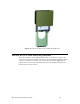
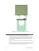
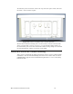
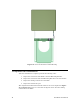
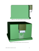
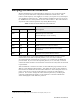
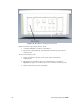
Table Of Contents
- Welcome
- Audience
- Related Documentation
- FCC Notice
- RF Statements
- EMC and Safety Statements
- 1. Introduction
- 2. Installing Components and Troubleshooting
- 3. Pole Mount Installation
- 4. Pad Mount Installation
- Introduction
- Required Tools
- Installation Location
- Preparing the Transformer Pad
- Preparing for Installation
- Performing the Installation
- Extend Pad Mounting Bracket
- Attach Pad Mounting Bracket to Lifting Nut
- Attach Conduit Housing to Pad Mounting Bracket
- Insert Conduit Thread into Conduit Housing
- Attach ECN to Pad Mounting Bracket
- Secure ECN to Pad Mounting Bracket
- Connect the ECN to Power and the Network
- Close and Lock the Conduit Housing
- Complete the Installation
- Verifying Successful Installation
- 5. Field Replacement for an ECN 7000 Series Device
- A. ECN 7000 Series Specifications
- B. Safety and High-Voltage Warnings
- C. ESD and Battery Warnings

44 Pad Mount Installation
Figure 21. Secure the ECN to the Pad Mounting Bracket
Connect the ECN to Power and the Network
You make the connections to power and to the communications network at the
bottom of the ECN, which is inside the Conduit Housing. All Echelon supplied
connectors are IP67 rated. Each connector has a cap designed to maintain its
long-term reliability. Figure 22 on page 45 shows the bottom of a typical ECN,
before installation.
You can connect the ECN to either low voltage, or with the CT option, medium
voltage.
The exact configuration of the ECN bottom panel depends on the options that you
have installed in the ECN, but at a minimum, the bottom panel has a connection
for power. In the figure, the upper left connection is for power.