
Installation Guide
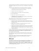
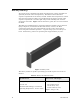
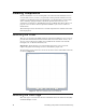
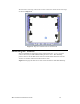
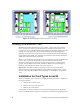
Table Of Contents
- Welcome
- Audience
- Related Documentation
- FCC Notice
- RF Statements
- EMC and Safety Statements
- 1. Introduction
- 2. Installing Components and Troubleshooting
- 3. Pole Mount Installation
- 4. Pad Mount Installation
- Introduction
- Required Tools
- Installation Location
- Preparing the Transformer Pad
- Preparing for Installation
- Performing the Installation
- Extend Pad Mounting Bracket
- Attach Pad Mounting Bracket to Lifting Nut
- Attach Conduit Housing to Pad Mounting Bracket
- Insert Conduit Thread into Conduit Housing
- Attach ECN to Pad Mounting Bracket
- Secure ECN to Pad Mounting Bracket
- Connect the ECN to Power and the Network
- Close and Lock the Conduit Housing
- Complete the Installation
- Verifying Successful Installation
- 5. Field Replacement for an ECN 7000 Series Device
- A. ECN 7000 Series Specifications
- B. Safety and High-Voltage Warnings
- C. ESD and Battery Warnings

20 Installing Components and Troubleshooting
Installing Components
Because the ECN’s cover is not designed to be removed in the field (the cover is
secured with one-way screws), you generally cannot perform in-field service for
an ECN. If an ECN becomes non-operational, you should replace it in the field
with a similarly equipped model to maintain operational service for your
customers; see Chapter 5, Field Replacement for an ECN 7000 Series Device, on
page 49. You can return the non-operational ECN to your service center for
maintenance.
The following sections describe how to install components in an ECN unit before
field deployment.
Removing the Cover
The cover is secured to the ECN enclosure with four #10 (M5) one-way screws to
prevent their unauthorized removal in the field. To remove these screws, use a
one-way screw removal tool, which are available from vendors such as W.W.
Grainger
®
, Inc. or Hudson Fasteners, Inc.
Important: Removing the cover compromises the factory seal. You must
replace the gasket and sealing screws to reestablish a proper seal.
To remove the cover, remove the screws at the four corners of the ECN enclosure,
as shown in Figure 8.
Figure 8. Top View of ECN with Cover Attached
Removing the Card Cage
The card cage is secured to the interior of the ECN enclosure with four #10 (M5)
standard Phillips
®
screws.