
User's Manual
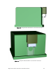


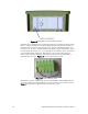


Table Of Contents
- Welcome
- Audience
- Related Documentation
- FCC Compliance Notice
- RF Statements
- EMC and Safety Statements
- Declaration of Conformity
- Introduction
- Pole Mount Installation
- Pad Mount Installation
- Introduction
- Required Tools
- Installation Location
- Preparing the Transformer Pad
- Preparing for Installation
- Performing the Installation
- Extend Pad Mounting Bracket
- Attach Pad Mounting Bracket to Lifting Nut
- Attach Conduit Housing to Pad Mounting Bracket
- Insert Conduit Thread into Conduit Housing
- Attach ECN to Pad Mounting Bracket
- Secure ECN to Pad Mounting Bracket
- Connect the ECN to Power and the Network
- Close and Lock the Conduit Housing
- Complete the Installation
- Verifying Successful Installation
- Field Replacement for an ECN 7000 Series Device
- ECN 7000 Series Specifications
- Safety and High-Voltage Warnings
- ESD and Battery Warnings

Edge Control Node 7000 Series Installation Guide 27
Replacing a Pad-Mounted ECN
Important: Before replacing an ECN in the field, visually inspect the unit and its
surroundings to ensure that the unit is not damaged and that it is safe to handle.
You do not need to reinstall the Pad Mounting Bracket to replace an ECN unit.
To remove a pad-mounted ECN:
1. If possible, use the ECoS system software to shut down the unit
remotely, before beginning field replacement.
2. Unlock the Conduit Housing and open the Conduit Housing door.
3. Remove all network connections from the bottom of the unit.
4. Remove the power connection from the unit.
5. Remove the screws at the bottom of the unit. These screws will remain
attached to the ECN.
6. Lift the ECN from the Pad Mounting Bracket.
To install a replacement pad-mounted ECN:
1. Attach the ECN to the Pad Mounting Bracket, as described in
Attach
ECN to Pad Mounting Bracket
on page 18.
2. Secure the ECN to the Pad Mounting Bracket using the screws at the
bottom of the unit, as described in
Secure ECN to Pad Mounting Bracket
on page
19.
3. Connect the ECN to power and to the network, as described in
Connect
the ECN to Power and the Network
on page 20.
4. Close the Conduit Housing and lock the door, as described in
Close and
Lock the Conduit Housing
on page 21.
5. Verify successful installation, as described in
Verifying Successful
Installation
on page 24.
Replacing the Battery Pack
To allow the ECN to run continuously, regardless of external power conditions,
the ECN includes a backup battery option. If your ECN includes this option, you
will occasionally need to replace the batteries.
The battery packs are located in their own dedicated compartment accessible
from the outside of the ECN enclosure, as shown in
Figure 15 on page 28. Within
this compartment, an electrical connector on a flying lead allows easy installation
of each battery pack. This separate compartment is weather tight and provides
shielding from sensitive electronics and transceivers.