
Operating Guide


13
PLEASE NOTE: 45H IS FOR OUTDOOR PERMANENT INSTALLATIONS ONLY AND 45HI IS FOR INDOOR PERMANENT INSTALLATIONS ONLY. THIS MANUAL
AND ALL ECCOTEMP CONTECT IS SUBJECT TO CHANGE WITHOUT NOTICE. PLEASE VISIT WWW.ECCOTEMP.COM/SUPPORT FOR MORE INFORMATION.
Support: Eccotemp.com/help-desk Shop Online: Eccotemp.com/products Store Locator: Eccotemp.com/locator
Phone: 866-356-1992 | Email: Support@eccotemp.com | Address: 315 - A Industrial RD Summerville, SC 29483
English
WARNING : Moisture in the ue
gas will condense as it leaves the vent
terminal. In cold weather this condensate
can freeze on the exterior wall, under
the eaves and on surrounding objects.
Some discoloration to the exterior of
the building is to be expected. However,
improper location or installation can
result in severe damage to the structure
or exterior nish of the building. Code
requirements are subject to change and
may vary by location.
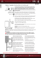
Leak Testing
WARNING: Never use an open ame to test for gas leaks, as property damage, personal
injury, or death could result.
The water heater and its gas connections must be leak tested at normal operating pressures before
it is placed in operation.
• Turn on the gas shut-o valve(s) to the water heater.
• Use a commercial leak detector or soapy water solution to test for leaks at all connections and ttings.
Bubbles indicate a gas leak that must be corrected.
The factory connections should also be leak tested after the water heater is placed in operation.
High Altitude
Ratings of gas water heaters are based on sea level operation and need not be changed for installations at
elevations up to 2,000 feet.
Unit not recommended for elevations in excess of 2,000 feet
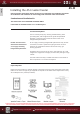
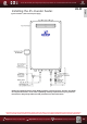
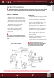
Installing the water heater.
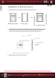
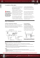
Flue Terminal Location
The location of the vent terminal depends on the following minimum clearances and considerations
(see illustration):
• Twelve (12) inches above grade level and above normal snow levels.
• Four (4) feet below, or four (4) feet horizontally from any door,
window, sot, under eave vent or gravity air inlet to the building
or other appliances, or from gas or electric meters. Do not locate
vent above walkways, doors, windows, air inlets, gas or electric
meters or other equipment.
• Ten (10) feet from any forced air inlet to the building. Any fresh or
make-up air inlet such as for a dryer or furnace area
is considered to be a forced air inlet.
• Eighteen (18) inches from an inside corner formed by two exterior walls.
• DO NOT install vent terminal under any patio/deck or too close
to shrubbery, as ue gases or condensate vapor may become a
nuisance or hazard and may cause property damage. Condensate
vapor could cause damage and be detrimental to the operation of
regulators, relief valves, or other equipment.
• To help prevent moisture from freezing on walls and under eaves,
do not locate vent terminal on the side of a building
with prevailing winter winds. The water heater must be located as
close as practicable to a chimney or gas vent.
• Caulk all cracks, seams and joints within six (6) feet of vent terminal.
• All painted surfaces should be primed to lessen the chance of
physical damage. Painted surfaces will require maintenance.
• Use of cellular core PVC (ASTM F891), cellular core CPVC, or
Radel (polyphenylsulfone) in non-metallic venting systems is
prohibited. Covering non-metallic vent pipe and ttings with
thermal insulation is prohibited.
• DO NOT connect to a chimney ue serving a separate appliance
designed to burn solid fuel.
Additional Considerations
45-H