
User`s manual


EC-520 User’s Manual
- 35 -
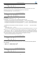
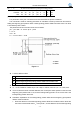
position offset from the beginning print-position is same with the inherent mechanical
value Q
0
of the printer (shown as figure 7-2) , all the offset value set by “GS ( F”
command is 0.
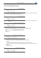
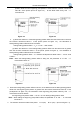
2. (1) When the distance L of the tearing/cutting position offset from the black mark is less than
the inherent mechanical value L
0
of the printer (shown as figure 7-3), the calculation of
tearing/cutting position offset is shown as follows:
tearing/cutting position offset =(L
0
-L)/0.176 (dots number)
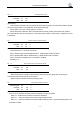
(2) When the distance L of the tearing/cutting position offset from the black mark is greater
than the inherent mechanical value L
0
of the printer (shown as figure 4), the calculation of
tearing/cutting position offset is shown as follows:
tearing/cutting position offset =(L
0
+ distance of adjacent two black mark -L)/0.176(dots
number)
Note: When the tearing/cutting position offset is being set, the parameter “a” of “GS ( F”
command should be “2”.
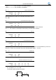
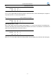
3. When the tearing/cutting position offset is not zero, or the distance Q of the tearing/cutting position
offset from the beginning print-position is greater than the inherent mechanical value Q
0
of the
printer(shown as figure 7-5), the calculation of the beginning print-position offset by “GS ( F”
command is shown as follows:
the beginning print-position offset =(Q- Q
0
)/0.176+ tearing/cutting position offset
Note: When setting the beginning print-position offset, the parameter “a” of “GS ( F” command
should be “1”.
4. The inherent mechanical value
of the printer: L
0
=A (mm) Q
0
=C (mm) (shown as figure 7-1).
Figure 7-2
Figure 7-3
Figure 7-5
Figure 7-4