
User`s manual

EC-520 User’s Manual
- 19 -
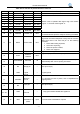
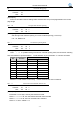
Table A-2 Pin function of parallel interface connector
Pin return Signal name Direction Description
1 19 /STROBE Data selected IN Width of selected pluse is 0.5 µ sec.
2 20 DATA1 Date bit 1 IN / OUT
3 21 DATA2 Date bit 2 IN / OUT
4 22 DATA3 Date bit 3 IN / OUT
5 23 DATA4 Date bit 4 IN / OUT
6 24 DATA5 Date bit 5 IN / OUT
7 25 DATA6 Date bit 6 IN / OUT
8 26 DATA7 Date bit 7 IN / OUT
9 27 DATA8 Date bit 8 IN / OUT
Means 8 bits of parallel data signal. High level means
logical “1”, low level means logical “0”.
10 28 /ACKNLG Answer out OUT
Pluse width is about 12µ sec. Low level means that data
is received and the printer is ready for receiving more data.
11
29
BUSY Printer state OUT
High level out means that printer is busy and can’t receive
data. High level is out from this pin on the following
condition:
1. When data is being imported;
2. At the time of printing;
3. When the printer is offline;
4. When error happens.
12 30 PE Paper out OUT High level means paper out.
13 SLCT
Printer is
selected
OUT
High level (5V) with the 3.3KΩpull-up resistor.
14
/AUTOFEED Auto feed IN
At low level, the printer will change to the next line to print
automatically after one line printing is finished.
15
16
NC
GND
Empty pin
Logical
ground
---
---
This pin is empty.
Logical ground
17 CHASSIS
Structure
ground
---
It is structure ground of printer, and is separated from
logical ground.
18 NC
Empty pin
---
This pin is empty.
19~30
GND
Ground
---
Loop ground that is twisted with signal line.
31 16 /INIT
Initialization of
printer
Input Low level means initialization of printer