
Tus neeg siv phau ntawv
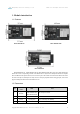
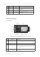

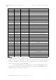
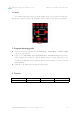
Table Of Contents

Chengdu Ebyte Electronic Technology Co.,Ltd ESP32 series development board User manual
Copyright ©2012–2022,Chengdu Ebyte Electronic Technology Co.,Ltd
4
5
Micro USB connector
The USB port can be used as the power supply for the circuit
board or the communication port for connecting the PC to the
ESP32 series module.
6
5V Power On LED
When the development board is powered on (USB or external 5
V), the indicator will light up. See schematics in related
documents for more information.
7
I/O
Most of the pins of the on-board module have been drawn to
the development board's row pins. Users can program ESP32 to
realize PWM, ADC, DAC, I2C, I2S, SPI and other functions.
Note: For specific function instructions, refer to the user manual of the ESP32 series
corresponding module.
2.2 Pin definition
The following is a front view of ESP32-WROOM-32E-TB as an example:
Figure 2. Current test interface diagram
Pin number
Pin name
Type
Pin description
1
3V3
P
3.3 V power supply
2
EN
I
CHIP_PU, Reset
3
VP
I
GPIO36, ADC1_CH0, S_VP
4
VN
I
GPIO39, ADC1_CH3, S_VN
5
IO34
I
GPIO34, ADC1_CH6, VDET_1
6
IO35
I
GPIO35, ADC1_CH7, VDET_2