
Datasheet

Product Data Sheet RG90-18/06
01/31/2019 page 5 of 8
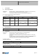
3 Operating Data
3.1 Electrical Operating Data
Measurement
conditions:
Normal air density = 1,2 kg/m3; Temperature 23°C +/- 3°C; Motor axis horizontal;warm-up
time before measuring 5 minutes (unless otherwise specified).
In the intake and outlet area should not be any solid obstruction within 0,5 m.
∆p = 0: corresp. to free air flow (see chapter aerodynamics)
I: corresp. to RMS line current
Features Condition Symbol Values
Frequency ∆p = 0 f 50 Hz 60 Hz
115 V 115 V
Nominal voltage
+- 10 % +- 10 %
Tolerance
∆p = 0 U
N
Power consumption 22 W 22 W
Tolerance
∆p = 0 P
+ 5 % - 10 % + 5 % - 10 %
Speed 2.200 1/min 1.900 1/min
+- 3 % +- 3 %
Tolerance
∆p = 0 n
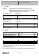
3.2 Electrical Features
Locked rotor protection Impedance
Locked rotor current at
3.3 Aerodynamics
Measurement
conditions:
Measured with a double chamber intake rig acc. to DIN EN ISO 5801.
Normal air density = 1,2 kg/m3; Temperature 23°C +/ - 3°C;
In the intake and outlet area should not be any solid obstruction within 0,5 m. Motor shaft
horizontal.
The information is only valid under the specified test conditions and may be changed by the
installation conditions. If there are deviations from the standard test conditions, the
characteristic values must be checked under the installed conditions.
a.) Operation condition:
2.200 1/min at free air flow Frequency: 50 Hz
Max. free-air flow (∆p = 0 /
= max.) 54,0 m3/h
Max. static pressure (∆p = max. /
=0) 90 Pa
b.) Operation condition:
1.900 1/min at free air flow Frequency: 60 Hz
Max. free-air flow (∆p = 0 /
= max.) 46,0 m3/h
Max. static pressure (∆p = max. /
=0) 130 Pa