
Datasheet

Product Data Sheet RG225-55/14/2TDMLO
02/01/2019 page 7 of 13
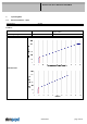
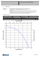
Speed control:
By analog voltage 0 - 10 V
Information to the curve analog:
0 V - < 1,3 V: 0 1/min
1,3 V: 800 1/min (Fan on, comming from von 0 V)
1,3 V - 1,6 V: 800 1/min (corresponding to min. speed)
1,6 V - 9,4 V: linear increasing curve
9,4 V - 10 V: 2500 1/min (corresponding to max. speed)
1,3 V - > 1,0 V: linear decreasing curve (comming from 10 V)
1,0 V: 600 1/min or 0 1/min (Fan off, comming from 10 V)
All values are measured in the housing!
*)Fan doesn't have a sensor break detection!
=> open Control Input = 0rpm!
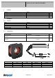
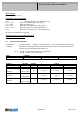
3.2 Electrical Operating Data
Measurement
conditions:
Normal air density = 1,2 kg/m3; Temperature 23°C +/ - 3°C; Motor axis horizontal; warm-up
time before measuring 5 minutes (unless otherwise specified). In the intake and outlet area
should not be any solid obstruction within 0,5 m.
∆p = 0:
corresp. to free air flow (see chapter aerodynamics)
I:
corresp. to arithm. mean current value
Name Condition
U Contr. 0001 U Contr.: 10 V
Features Condition Symbol Values
Voltage range U 16 V 36 V
Nominal voltage U
N
24 V
Power consumption 44 W 90 W 87 W
+- 10 % +- 10,0 % +- 10,0 %
Tolerance
∆p = 0
U Contr. 0010
P
Current consumption 2.700 mA 3.750 mA 2.400 mA
+- 10,0 % +- 10,0 % +- 10,0 %
Tolerance
∆p = 0
U Contr. 0010
I
Speed 2.000 1/min 2.500 1/min 2.500 1/min
+- 10,0 % +- 5,0 % +- 5,0 %
Tolerance
∆p = 0
U Contr. 0010
n