
Datasheet

Product Data Sheet RG190-39/18/2TDMLO
01/31/2019 page 6 of 14
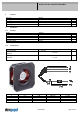
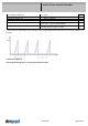
Schematics
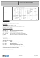
Input voltage divider:
R1 = 47 kOhm
R2 = 36 kOhm
For protection: There is parallel to R2 a 5,1 V Z-Diode
Speed control:
By pulse-width modulation (PWM) 0 ... 100%
with switching transistor in emitter circuit and collector resistance to 12 V
Frequency = 2 kHz (1 - 10 kHz)
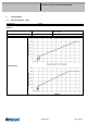
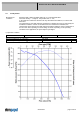
Information to the curve PWM:
0% - <10% PWM: 0 1/min
10% PWM: 800 1/min (Fan on, comming from 0% PWM)
10% - 13% PWM: 800 1/min (corresponding to min. speed)
13% - 78% PWM: linear increasing curve
78% - 100% PWM: 3.000 1/min (corresponding to max. speed)
10% - >8% PWM: linear decreasing curve (comming from 100% PWM)
8% PWM: 600 1/min or 0 1/min (Fan off, comming from 100% PWM)
or:
Speed control:
By analog voltage 0 - 10 V
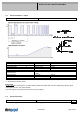
Information to the curve analog:
0 V - < 1,3 V: 0 1/min
1,3 V: 800 1/min (Fan on, comming from von 0 V)
1,3 V - 1,6 V: 800 1/min (corresponding to min. speed)
1,6 V - 9,4 V: linear increasing curve
9,4 V - 10 V: 3.000 1/min (corresponding to max. speed)
1,3 V - > 1,0 V: linear decreasing curve (comming from 10 V)
1,0 V: 600 1/min or 0 1/min (Fan off, comming from 10 V)
All measurement values are measured in the housing!
Fan has no sensor break detection!