Product Data Sheet RG190-39/18/2TDMLO Product Data Sheet RG190-39/18/2TDMLO The engineer's choice
Product Data Sheet RG190-39/18/2TDMLO RG190-39/18/2TDMLO INDEX 1 General ............................................................................................................................................................... 3 2 Mechanics .......................................................................................................................................................... 3 2.1 2.2 3 Operating Data ............................................................................
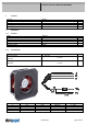
Product Data Sheet RG190-39/18/2TDMLO 1 General Fan type Rotating direction looking at rotor Airflow direction Bearing system Mounting position - shaft 2 Mechanics 2.1 General Width Height Depth Mass Housing material Impeller material 2.
Product Data Sheet RG190-39/18/2TDMLO The auxilliaries shown on the schematic diagram (which are required for the intended use) are not part of our delivery.
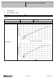
Product Data Sheet RG190-39/18/2TDMLO 3 Operating Data 3.
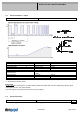
Product Data Sheet RG190-39/18/2TDMLO Schematics Input voltage divider: R1 = 47 kOhm R2 = 36 kOhm For protection: There is parallel to R2 a 5,1 V Z-Diode Speed control: By pulse-width modulation (PWM) 0 ... 100% with switching transistor in emitter circuit and collector resistance to 12 V Frequency = 2 kHz (1 - 10 kHz) Information to the curve PWM: 0% - <10% PWM: 0 1/min 10% PWM: 800 1/min (Fan on, comming from 0% PWM) 10% - 13% PWM: 800 1/min (corresponding to min.
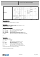
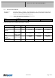
Product Data Sheet RG190-39/18/2TDMLO 3.2 Electrical Operating Data Measurement conditions: ∆p = 0: I: Name U Contr. 0001 Normal air density = 1,2 kg/m3; Temperature 23°C +/ - 3°C; Motor axis horizontal; warm-up time before measuring 5 minutes (unless otherwise specified). In the intake and outlet area should not be any solid obstruction within 0,5 m. corresp. to free air flow (see chapter aerodynamics) corresp. to arithm. mean current value Condition U Contr.
Product Data Sheet RG190-39/18/2TDMLO 3.3 Electrical Interface - Output Tacho type Features Tacho operating voltage Tacho signal Low Tacho signal High Maximum sink current Maximum source current External resistor Tacho frequency Tacho isolated from motor Slew rate /2 (open collector) Note UBS US low US high Isink Values <= 57 V I sink: 2 mA <=0,4 V I source: 0 mA <=57 V <= 20 mA 0 mA External resistor Ra from UBS to US required. All voltages measured to GND.
Product Data Sheet RG190-39/18/2TDMLO Max. residual current at UN Locked rotor protection Locked rotor current at UN Clock signal at locked rotor Internal fuse Voltage control *) IF <= 5 mA Auto restart Iblock approx. 1.600 mA t3 / t4 typical: 6,5 s / 10,0 s Littelfuse NANO2 > Very Fast-Acting > 451/453 Series 3,5A / 125V (Art.No.: 045103.
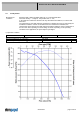
Product Data Sheet RG190-39/18/2TDMLO 3.5 Aerodynamics Measurement conditions: Measured with a double chamber intake rig acc. to DIN EN ISO 5801. Normal air density = 1,2 kg/m3; Temperature 23°C +/ - 3°C; In the intake and outlet area should not be any solid obstruction within 0,5 m. Motor shaft horizontal. The information is only valid under the specified test conditions and may be changed by the installation conditions.
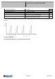
Product Data Sheet RG190-39/18/2TDMLO 3.6 Sound Data Measurement conditions: Sound pressure level: 1 meter distance between microphone and the air intake. Sound power level: Acc. to DIN 45635 part 38 (ISO 10302) Measured in a semianchoic chamber with a background noise level of Lp(A) < 5 dB(A) For further measurement conditions see chapter aerodynamics. a.) Operation condition: 3.000 1/min at free air flow U Contr.
Product Data Sheet RG190-39/18/2TDMLO Kind According Ceck accuracy / Limit Result Electrostatic Discharge Immunity Test DIN EN 61000-4-2:2001-12 Contact Discharge +/- 4 kV; Air Discharge +/- 8 kV A: The monitored function operates as designed during and after exposure to a disturbance.
Product Data Sheet RG190-39/18/2TDMLO 5 Safety 5.1 Electrical Safety Dielectric strength DIN EN 60950 (VDE 0805) and DIN EN 60335 (VDE 0700) A.) Type test Measuring conditions: After 48h of storage at 95% R.H. and 25°C. No arcing or breakdown is allowed! All connections together to ground. B.) Routine test Measuring conditions: At indoor climate. No arcing or breakdown is allowed! All connections together to ground. Isolation resistance Measuring conditions: After 48h of storage at 95% R.H.