
Datasheet

Product Data Sheet RG160-28/14NTDT
01/31/2019 page 5 of 9
3.2 Electrical Operating Data
Measurement
conditions:
Normal air density = 1,2 kg/m3; Temperature 23°C +/ - 3°C; Motor axis horizontal; warm-up
time before measuring 5 minutes (unless otherwise specified). In the intake and outlet area
should not be any solid obstruction within 0,5 m.
∆p = 0:
corresp. to free air flow (see chapter aerodynamics)
I:
corresp. to arithm. mean current value
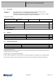
Name Condition
TU 0001 TU: >= 50 °C
NTC 0001
>=50 °C or broken lead wire (R = oo; means open con trol input)
No inrush current means: Inrush current is mainly affected by length and kind of connecting line and the 470uF
capacitor.
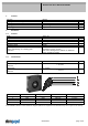
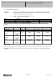
Features Condition Symbol Values
Voltage range U 16 V 28 V
Nominal voltage U
N
24 V
Power consumption 53,1 W 64 W 60,2 W
+- 15 % +- 15,0 % +- 15,0 %
Tolerance
∆p = 0
TU / NTC
0010
P
Current consumption 3.320 mA 2.650 mA 2.150 mA
+- 15,0 % +- 15,0 % +- 15,0 %
Tolerance
∆p = 0
TU / NTC
0010
I
Speed 4.060 1/min 4.200 1/min 4.200 1/min
+- 10,0 % +- 10,0 % +- 10,0 %
Tolerance
∆p = 0
TU / NTC
0010
n
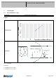
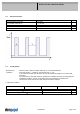
Motor testing
The motor testing relates to a fan, operating with horizontal shaft, at free wir flow. It is possible to run this motor in an
uncontrolled state. For some testings the motor may set in a test cycle by connecting to a voltage follower as below
mentioned.