Product Data Sheet RG160-28/14N/19TDR-382 Product Data Sheet RG160-28/14N/19TDR-382 The engineer's choice
Product Data Sheet RG160-28/14N/19TDR-382 RG160-28/14N/19TDR-382 INDEX 1 General ............................................................................................................................................................... 3 2 Mechanics .......................................................................................................................................................... 3 2.1 2.2 3 Operating Data ....................................................................
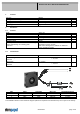
Product Data Sheet RG160-28/14N/19TDR-382 1 General Fan type Rotating direction looking at rotor Airflow direction Bearing system Mounting position - shaft 2 Mechanics 2.1 General Blower Counterclockwise Air in axially, Air out radially Ball bearing Any Width Height Depth Mass Housing material Impeller material Max. torque when mounted across both mounting flanges; Metal flange on mounting plate Screw size 2.
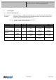
Product Data Sheet RG160-28/14N/19TDR-382 3 Operating Data 3.1 Electrical Operating Data Measurement conditions: ∆p = 0: I: Features Voltage range Nominal voltage Power consumption Tolerance Current consumption Tolerance Speed Tolerance Normal air density = 1,2 kg/m3; Temperature 23°C +/ - 3°C; Motor axis horizontal; warm-up time before measuring 5 minutes (unless otherwise specified). In the intake and outlet area should not be any solid obstruction within 0,5 m. corresp.
Product Data Sheet RG160-28/14N/19TDR-382 3.2 Electrical Interface - Output Alarm type /19 (low = ok, open collector inverse) Features Note Alarm operating voltage UBA Alarm signal Low Alarm signal High Maximum sink current Maximum source current UA low UA high Isink External resistor Alarm start-up delay time t6 Tolerance Alarm trip speed limit Values Min.: 4,0 V I sink: 2 mA I source: 0 mA >= 0,4 V 28,0 V >= 20 mA 0 mA External resistor Ra from UBA to UA required.
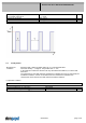
Product Data Sheet RG160-28/14N/19TDR-382 Reversed polarity protection Max. residual current at UN Locked rotor protection Locked rotor current at UN Clock signal at locked rotor 3.4 P-CH FET IF >= 5 mA Auto restart Iblock approx. 450 mA t3 / t4 typical: 0,5 s / 5,0 s Aerodynamics Measurement conditions: Measured with a double chamber intake rig acc. to DIN EN ISO 5801.
Product Data Sheet RG160-28/14N/19TDR-382 3.5 Sound Data Measurement conditions: Sound pressure level: 1 meter distance between microphone and the air intake. Sound power level: Acc. to DIN 45635 part 38 (ISO 10302) Measured in a semianchoic chamber with a background noise level of Lp(A) < 5 dB(A) For further measurement conditions see chapter aerodynamics. a.) Operation condition: 4.
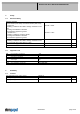
Product Data Sheet RG160-28/14N/19TDR-382 5 Safety 5.1 Electrical Safety Dielectric strength DIN EN 60950 (VDE 0805) and DIN EN 60335 (VDE 0700) A.) Type test Measuring conditions: After 48h of storage at 95% R.H. and 25°C. No arcing or breakdown is allowed! All connections together to ground. B.) Routine test Measuring conditions: At indoor climate. No arcing or breakdown is allowed! All connections together to ground. Isolation resistance Measuring conditions: After 48h of storage at 95% R.H.