
Datasheet

Product Data Sheet RET97-25/18/2TDMPU
02/01/2019 page 6 of 15
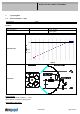
0 % - 7% PWM: 0 1/min
7 % - 10% PWM: 800 1/min (corresponding to min. speed)
10 % - 90% PWM: linear increasing curve
90 % - 100% PWM: 5.300 1/min (corresponding to max. speed)
7 % PWM: 800 1/min (Fan on, comming from 0% PWM)
5 % PWM: 600 1/min or 0 1/min (Fan off, comming from 100% PWM)
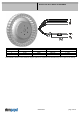
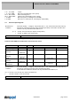
3.2 Electrical Operating Data
Measurement
conditions:
Normal air density = 1,2 kg/m3; Temperature 23°C +/ - 3°C; Motor axis horizontal; warm-up
time before measuring 5 minutes (unless otherwise specified). In the intake and outlet area
should not be any solid obstruction within 0,5 m.
∆p = 0:
corresp. to free air flow (see chapter aerodynamics)
I:
corresp. to arithm. mean current value
Name Condition
PWM 0001 PWM: 100 %;
100% PWM or broken lead wire (open control input); f = 2kHz
The data at 50% PWM are no FK features and need not be tested.
Features Condition Symbol Values
Voltage range U
Nominal voltage U
N
48 V
Power consumption 120 W
Tolerance
∆p = 0
PWM 0010
P
Current consumption 2.500 mA
Tolerance
∆p = 0
PWM 0010
I
Speed 5.300 1/min
Tolerance
∆p = 0
PWM 0010
n
Starting current
consumption
3.700 mA
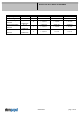
Measurement
conditions:
Normal air density = 1,2 kg/m3; Temperature 23°C +/ - 3°C; Motor axis horizontal; warm-up
time before measuring 5 minutes (unless otherwise specified).
In the intake and outlet area should not be any solid obstruction within 0,5 m.
∆p = 0: corresp. to free air flow (see chapter aerodynamics)
I: corresp. to arithm. mean current value
Name Condition
PWM 0001 PWM: 100 %;
The data at 50% PWM are no FK features and need not be tested.