Product Data Sheet RET97-25/14/2TDP-052 Product Data Sheet RET97-25/14/2TDP-052 The engineer's choice
Product Data Sheet RET97-25/14/2TDP-052 RET97-25/14/2TDP-052 INDEX 1 General ............................................................................................................................................................... 3 2 Mechanics .......................................................................................................................................................... 3 2.1 2.2 3 Operating Data ........................................................................
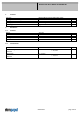
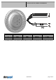
Product Data Sheet RET97-25/14/2TDP-052 1 General Fan type Rotating direction looking at rotor Airflow direction Bearing system Mounting position - shaft 2 Mechanics 2.1 General Depth Diameter Mass Housing material Impeller material 2.
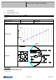
Product Data Sheet RET97-25/14/2TDP-052 Wire 1 2 3 4 Color red blue violet white Operation + UB - GND PWM Tacho Wire size AWG 18 AWG 18 AWG 22 AWG 22 Insulation diameter 2,2 mm 2,2 mm 1,7 mm 1,7 mm The auxilliaries shown on the schematic diagram (which are required for the intended use) are not part of our delivery.
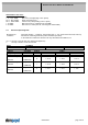
Product Data Sheet RET97-25/14/2TDP-052 3 Operating Data 3.1 Electrical Interface - Input Control input PWM Features Inpute type PWM - Frequency Open collector 1 kHz - 10 kHz typical: 2 kHz Characteristics Schematics Speed control: By Puls width modulation (PWM) 0 ...
Product Data Sheet RET97-25/14/2TDP-052 Information to the curve: 0 % - 7% PWM: 0 1/min 7 % - 10% PWM: 800 1/min (corresponding to min. speed) 10 % - 90% PWM: linear increasing curve 90 % - 100% PWM: 6.000 1/min (corresponding to max. speed) 7 % PWM: 800 1/min (Fan on, comming from 0% PWM) 5 % PWM: 600 1/min or 0 1/min (Fan off, comming from 100% PWM) 3.
Product Data Sheet RET97-25/14/2TDP-052 3.3 Electrical Interface - Output Tacho type Features Tacho operating voltage Tacho signal Low Tacho signal High Maximum sink current Maximum source current External resistor Tacho frequency Tacho isolated from motor Slew rate /2 (open collector) Note UBS US low US high Isink Values <= 32 V I sink: 2 mA <=0,4 V I source: 0 mA <=32 V <= 20 mA 0 mA External resistor Ra from UBS to US required. All voltages measured to GND.
Product Data Sheet RET97-25/14/2TDP-052 Max. residual current at UN Locked rotor protection Locked rotor current at UN Clock signal at locked rotor IF <= 5 mA Auto restart Iblock approx. 1.700 mA t3 / t4 typical: 8,2 s / 10 s Locked rotor signal t5: After 4 failed start-ups there is an extended timeout of 40 s.
Product Data Sheet RET97-25/14/2TDP-052 02/01/2019 page 9 of 14
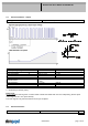
Product Data Sheet RET97-25/14/2TDP-052 3.5 Aerodynamics Measurement conditions: Measured with a double chamber intake rig acc. to DIN EN ISO 5801. Normal air density = 1,2 kg/m3; Temperature 23°C +/ - 3°C; In the intake and outlet area should not be any solid obstruction within 0,5 m. Motor shaft horizontal. The information is only valid under the specified test conditions and may be changed by the installation conditions.
Product Data Sheet RET97-25/14/2TDP-052 02/01/2019 page 11 of 14
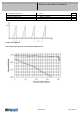
Product Data Sheet RET97-25/14/2TDP-052 3.6 Sound Data Measurement conditions: Sound pressure level: 1 meter distance between microphone and the air intake. Sound power level: Acc. to DIN 45635 part 38 (ISO 10302) Measured in a semianchoic chamber with a background noise level of Lp(A) < 5 dB(A) For further measurement conditions see chapter aerodynamics. a.) Operation condition: 5.
Product Data Sheet RET97-25/14/2TDP-052 5 Safety 5.1 Electrical Safety Dielectric strength DIN EN 60950 (VDE 0805) and DIN EN 60335 (VDE 0700) A.) Type test Measuring conditions: After 48h of storage at 95% R.H. and 25°C. No arcing or breakdown is allowed! All connections together to ground. B.) Routine test Measuring conditions: At indoor climate. No arcing or breakdown is allowed! All connections together to ground. Isolation resistance Measuring conditions: After 48h of storage at 95% R.H.