
Datasheet

Product Data Sheet RER175-42/14/2TDMLP
02/01/2019 page 6 of 14
Please note:
It's possible to control the fan by a control voltage of
0... 5 V. (5 V corresponds to 100 % PWM).
The power supply must be able to "sink" and works together with an internal pull-up resistor (4,7 kOhm).
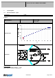
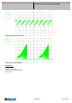
Information to the curve:
0 % - 7% PWM: 0 1/min
7 % PWM: 800 1/min (Fan on, comming from 0% PWM)
7 % - 10% PWM: 800 1/min (corresponding to min. speed)
10 % - 90% PWM: linear increasing curve
90 % - 100% PWM: 3.400 1/min (corresponding to max. speed)
7 % - 5 % PWM: linear decreasing curve (comming from 100% PWM)
5 % PWM: 600 1/min or 0 1/min (Fan off, comming from 100% PWM)
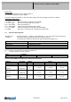
3.2 Electrical Operating Data
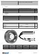
Measurement
conditions:
Normal air density = 1,2 kg/m3; Temperature 23°C +/ - 3°C; Motor axis horizontal; warm-up
time before measuring 5 minutes (unless otherwise specified).
In the intake and outlet area should not be any solid obstruction within 0,5 m.
Measurement setup: Measured between two steel plates
Steel plate: 180 mm x 180 mm
Intake nozzle: D: 125,5 mm; R: 10 mm
Distance between bottom and top plate: 80 mm
Overlapping impeller / nozzle: 2 mm
∆p = 0: corresp. to free air flow (see chapter aerodynamics)
I: corresp. to arithm. mean current value
Name Condition
PWM 0001 PWM: 95 %; f: 2 kHz
100% PWM; f = 2 kHz or broken lead wire (open control input)
The data at 50% PWM are no FK features and need not be tested.
Features Condition Symbol Values
Voltage range U 16 V 30,0 V
Nominal voltage U
N
24,0 V
Power consumption 33,6 W 48,0 W 49,2 W
+- 10,0 % +- 10,0 % +- 10,0 %
Tolerance
∆p = 0
PWM 0010
P
Current consumption 2.100 mA 2.000 mA 1.640 mA
+- 10,0 % +- 10,0 % +- 10,0 %
Tolerance
∆p = 0
PWM0010
I
Speed 3.000 1/min 3.400 1/min 3.400 1/min
+- 7,5 % +- 5,0 % +- 5,0 %
Tolerance
∆p = 0
PWM 0010
n