
Datasheet


Product Data Sheet RER160-28/14N/2TDA
02/01/2019 page 5 of 13
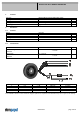
3.2 Electrical Operating Data
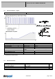
Measurement
conditions:
Normal air density = 1,2 kg/m3; Temperature 23°C +/ - 3°C; Motor axis horizontal; warm-up
time before measuring 5 minutes (unless otherwise specified).
In the intake and outlet area should not be any solid obstruction within 0,5 m.
Measurement setup: Measured between two steel plates
Steel plate: 260 mm x 260 mm
Intake nozzle: D: 100,0 mm; R: 5,0 mm
Distance between bottom and top plate: 52,6 mm
Overlapping impeller / nozzle: 2,0 mm
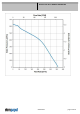
∆p = 0: corresp. to free air flow (see chapter aerodynamics)
I: corresp. to arithm. mean current value
Name Condition
U Contr. 0001 U Contr.: 10 V
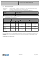
Features Condition Symbol Values
Voltage range U 16 V 28 V
Nominal voltage U
N
24 V
Power consumption 49,6 W 51 W 50,4 W
+- 15,0 % +- 15,0 % +- 15,0 %
Tolerance
∆p = 0
U Contr. 0010
P
Current consumption 3.100 mA 2.125 mA 1.800 mA
+- 15,0 % +- 15,0 % +- 15,0 %
Tolerance
∆p = 0
U Contr.0010
I
Speed 4.200 1/min 4.200 1/min 4.200 1/min
+- 7,5 % +- 7,5 % +- 7,5 %
Tolerance
∆p = 0
U Contr. 0010
n
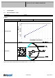
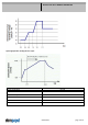
Motor testing
The motor testing relates to a fan, operating with horizontal shaft, at free wir flow. It is possible to run this motor in an
uncontrolled state. For some testings the motor may set in a test cycle by connecting to a voltage follower as below
mentioned.
Voltage graph to start the test cycle