
Datasheet

Product Data Sheet RER160-28/06S
01/31/2019 page 6 of 10
3.2 Electrical Features
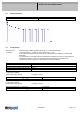
Locked rotor protection Thermal circuit breaker
Locked rotor current at
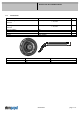
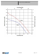
3.3 Aerodynamics
Measurement
conditions:
Measured with a double chamber intake rig acc. to DIN EN ISO 5801.
Normal air density = 1,2 kg/m3; Temperature 23°C +/ - 3°C;
In the intake and outlet area should not be any solid obstruction within 0,5 m. Motor shaft
horizontal.
The information is only valid under the specified test conditions and may be changed by the
installation conditions. If there are deviations from the standard test conditions, the
characteristic values must be checked under the installed conditions.
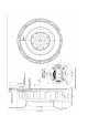
Measurement setup: Measured between two steel plates
Steel plate: 260 mm x 260 mm
Intake nozzle: D: 100 mm; R: 5 mm
Distance between bottom and top plate: 55 mm
Overlapping impeller / nozzle: 2 mm
a.) Operation condition:
2.800 1/min at free air flow Frequency: 50 Hz
Max. free-air flow (∆p = 0 /
= max.) 232,0 m3/h
Max. static pressure (∆p = max. /
=0) 240 Pa
b.) Operation condition:
3.250 1/min at free air flow Frequency: 60 Hz
Max. free-air flow (∆p = 0 /
= max.) 270,0 m3/h
Max. static pressure (∆p = max. /
=0) 350 Pa