
Datasheet


Product Data Sheet RER125-19/14N
02/01/2019 page 5 of 8
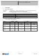
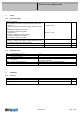
3.2 Electrical Features
Electronic function None
Reversed polarity protection Rectifying diode
Max. residual current at U
N
I
F
< 10 mA
Locked rotor protection Auto restart
Locked rotor current at U
N
I
block
approx. 900 mA
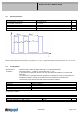
Clock signal at locked rotor
t
3
/ t
4
typical: 0,6 s / 10 s
Block1: special locked rotor protection: 5 cycles t3 / t4 = 0,6 s / 1 s Block2: locked rotor protection t3 / t4 = 0,6 s / 10 s
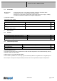
3.3 Aerodynamics
Measurement
conditions:
Measured with a double chamber intake rig acc. to DIN EN ISO 5801.
Normal air density = 1,2 kg/m3; Temperature 23°C +/ - 3°C;
In the intake and outlet area should not be any solid obstruction within 0,5 m. Motor shaft
horizontal.
The information is only valid under the specified test conditions and may be changed by the
installation conditions. If there are deviations from the standard test conditions, the
characteristic values must be checked under the installed conditions.
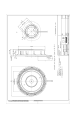
Measurement setup: Measured between two steel plates
Steel plate: 220 mm x 220 mm
Intake nozzle: D: 86 mm; R: 5 mm
Distance between bottom and top plate: 39 mm
Overlapping impeller / nozzle: 2 mm
a.) Operation condition:
2.650 1/min at free air flow
Max. free-air flow (∆p = 0 /
= max.) 105,0 m3/h
Max. static pressure (∆p = max. /
=0) 125 Pa