
Datasheet


Product Data Sheet 3412 NGMV
01/31/2019 page 5 of 10
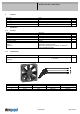
3.2 Electrical Operating Data
Measurement
conditions:
Normal air density = 1,2 kg/m3; Temperature 23°C +/ - 3°C; Motor axis horizontal; warm-up
time before measuring 5 minutes (unless otherwise specified). In the intake and outlet area
should not be any solid obstruction within 0,5 m.
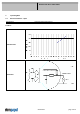
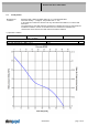
∆p = 0:
corresp. to free air flow (see chapter aerodynamics)
I:
corresp. to arithm. mean current value
Name Condition
TU 0001 TU: >= 50 °C
NTC 0001 NTC < 34 kOhm
Attention!
Fan and NTC must be exposed to the same ambient temperature. It's to exclude that the fan operate at higher
ambient temperature and the NTC is placed in a colder environment!
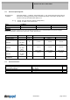
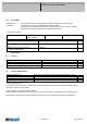
Features Condition Symbol Values
Voltage range U 8 V 14,0 V
Nominal voltage U
N
12,0 V
Power consumption 0,9 W 2,0 W 2,8 W
+- 20 % +- 20,0 % +- 20,0 %
Tolerance
∆p = 0
TU / NTC
0010
P
Current consumption 110 mA 167 mA 200 mA
+- 20,0 % +- 20,0 % +- 20,0 %
Tolerance
∆p = 0
TU / NTC
0010
I
Speed 1.500 1/min 2.300 1/min 2.700 1/min
+- 10,0 % +- 10,0 % +- 10,0 %
Tolerance
∆p = 0
TU / NTC
0010
n
Starting current
consumption
460 mA
3.3 Electrical Features
Electronic function Speed-Controlled
Reversed polarity protection Rectifying diode
Max. residual current at U
N
I
F
<= 50 uA
Locked rotor protection Auto restart
Locked rotor current at U
N
I
block
approx. 460 mA
Clock signal at locked rotor
t
3
/ t
4
typical: 0,23 s / 1,1 s