
Owner Manual

11
ASSEMBLY INSTRUCTIONS
10-1
10-2
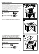
10. Burner Installation
10-1. Connect the gas hose and regulator (F) assembly to
the burner assembly and tighten the nut on the hose.
Line up holes in the burner assembly (C) with
corresponding holes in the table assembly, insert four
M5X12 screws (FF) through holes, tighten.
10-2. The assembled parts will look like figure 10-2.
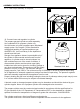
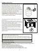
11-1. Screw the knob (A) to the lid (B) with M4 X 5
screws (BB). Pour glass (one pack) (I) into the
burner and put the lid above the burner assembly.
Hardware Used
FF
HH
x 4
x 1
M5X12 screw
Hardware Used
C
F
BB
M4 X 5 screw
x 1
Philips screwdriver
11-1
B
A
I
HH
x 1
Philips screwdriver
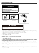
CAUTION:
Lid must be removed when burner is in operation.