
Owner Manual


Fire Table Manual | 11
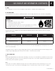
Flare Nut
Orifice
Venturi/Air shutter
er
D. LP GAS SUPPLY
• The pressure regulator and hose assembly supplied with LP models must be used. Replacement pressure regulators and hose
assemblies must be those specied in this manual.
• The LP gas supply cylinder used with LP models must be constructed and mark
ed in accordance with the specications for LP
gas cylinders of the U.S. Department of Transportation (DOT).
• Cylinders must be stored outdoors in a well ventilated area out of the reach of children. Disconnected cylinders must have
threaded valve plugs tightly installed and must not be stored in a building, garage or any other enclosed area.
• Storage of this appliance indoors is permissible only if it has been disconnected from its fuel supply (natural gas line or LP gas
cylinder).
• The LP gas cylinder supply system must be arranged for vapor withdrawal.
• The LP gas cylinder used must include a collar to protect the cylinder valve.
• When an LP model is not in use, the LP gas must be turned off at the supply cylinder.
• The specic size and capacity of the cylinder(s) to be used: 20 lb. or hard plumbed to propane tank.
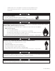
IMPROPER INSTALLATION, ADJUSTMENT, ALTERATION SERVICES, OR MAINTENANCE CAN CAUSE INJURY OR PROPERTY
DAMAGE. REFER TO AND UNDERSTAND THIS MANUAL. FOR ASSISTANCE OR ADDITIONAL INFORMATION CONSULT A
QUALIFIED INSTALLER, SERVICE AGENCY, LICENSED TECHNICIAN OR THE GAS SUPPLIER.
Gas Set-Up for Liquid Propane
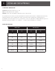
1. With burner in place in our fire pit table or other installation location and proper
sized orifice inserted in burner neck (see chart on page 6 for orifice sizing), locate
flexible rubber propane hose and regulator supplied with this burner.
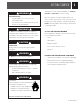
2. Attach the propane hose to incoming gas fitting on the gas valve. For our gas
valves and control panels, this is the lower fitting. Using two wrenches, one to hold
the valve and one to turn the valve fitting. Tighten securely.
3. Locate the metal flex-line gas hose and tighten securely to the top valve fitting
following the method described in step 2.
4. Using two wrenches, securely tighten the flare nut on the free end of the metal flex
hose to the orifice on the burner.
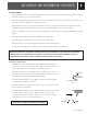
5. For liquid propane installations, the air shutter should be adjusted to 1/4” opening
as shown at right to prevent sooting. To adjust air shutter, loosen the small
securing screw and rotate air shutter to allow more or less airflow. Closing the
shutter will produce a more yellow flame but may soot.
-OR-
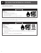
Outdoor GreatRoom Co. Control panel kit
Incoming gas
Out to burner
CHECK ENTIRE SYSTEM FOR LEAKS BEFORE OPERATING
Fire Table Key Valve
- OR -
OrceFlare Nut
Out to Burner
Incoming Gas
Venturi/Air Shutter
4GAS HOOK-UP AND INFORMATION (CONTINUED)