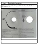
Part B IGNITION CONTROL BOARD Hero below is an exact visual display of the Operation Tablet as found on your Fire Table / Fire Column. Read carefully before using.
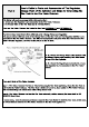
User's Guide to Parts and Accessories of The Regulator, Part C Charge Valve of the Cylinder and Steps to Connecting the Gas Tank to the Fire Table /Column. This Safety Information passage holds information that : 1) shows you the Regulator { per-connected to the Fire Table / Column ) 2 ) the Charge Valve of the Gas Tank and Its relevant Valves. There are Fire Table / Column that holds the Gas Tank INTERNALLY and EXTERNALLY. The Owner / User must know all the different parts : Charge Valves and Regulator.
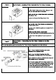
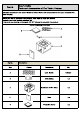
Part D User's Guide ; Loading of Gas Tank into the Fire Table / Column. The Fire Table / Column has a Door. Remove the Door and leave the Door on the floor. Inside, you will see a Metal Stand with per-attached Wing Screw / Nut. Proceed to Unscrew the Wing Screw / Nut Load the Gas Tank / Gas Cylinder as Indicated by the bold black arrow. Place the Tank / Cylinder gently and snugly into the Metal Stand. Position the Wing Screw / Nut in place. Turn the Wing Screw until fully tightens into the Nut.
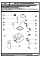
Part F. FIRE TABLE / COLUMN PARTS INTRODUCTION 'Your Fire Table / Column is delivered per-assembled whereby there is no assembly actions needed. Here below is an introduction to all the parts that forms your Fire Table / Column. Each part Is different and holds Its own function. DO NOT attempt to change and or remove any part(s) thereof. In the event of servicing and or operational Issues, contact Squalled Services Technical Support and or seek Qualified Service Technician.
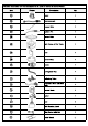
Tabulated here below are the description to all parts as shown in above Picture . tem Picture.
rt n rise of Fire column. Tabulated here below is the User's Guide to various Parts and Accessories to form your complete Fire Table /Column. Before you start to assemble this product, make sure all parts are present. Compare parts with package contents list. If any parts are missing or damaged, DO NOT attempt to assemble the product.
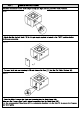
rt | N SON Tabulated here below are the basic steps to help you light and use your Fire Table / Column. STEP 1. Check that the Control Knob (13) for the gas supply system is turned to the “OFF” position before starting any assembly. " STEP 2 +/ 2. Put your hand into vent opening to lift and remove the Door from the Fire Table / Column (C). STEP 3 3. Place the 20lbs Propane Gas Tank (not included) into the Metal Stand (18). Make sure the Propane Gas Tank Is placed completely Into the Metal Stand (18 ).