DSA250i & DSA230i LOUDSPEAKER O W N E R ’S M A N U A L
DSAi Series Owner’s Manual Congratulations on the purchase of your new EAW loudspeaker. You now own one of the finest professional audio products available - the result of exceptional engineering and meticulous craftsmanship. Please read these instructions to get the maximum performance from your new loudspeaker. SAFETY PRECAUTIONS - READ THIS FIRST SAFETY INSTRUCTIONS Read and heed all warnings and safety instructions in the accompanying "EAW Loudspeaker Manual" before using this product.
ATTENZIONE: Il diffusore è completo di cavo d'alimentazione ac fornito in dotazione. In base la voltaggio del modello di diffusore acquistato, il cavo è configurato con il connettore ac più adeguato. Nel caso in cui il connettore non sia compatibile con le prese di corrente adottate nell'area d'impiego, rivolgersi ad un elettricista qualificato per ri-configurare il cavo con il connettore più appropriato. Assicurarsi che la presa di corrente sia adeguatamente collegata a terra.
EC DECLARATION OF CONFORMITY Eastern Acoustic Works, as the manufacturer, hereby certifies that, in their delivered versions, Product Models: DSA230i and DSA250i Product Description: Self-powered loudspeaker comply with the provisions of the standards listed below.
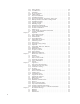
CONTENTS Safety Precautions - Read This First . . . . . . . . . . . . . . . . . . . . . . . . . . . . . . . . . . . EC Declaration of Conformity . . . . . . . . . . . . . . . . . . . . . . . . . . . . . . . . . . . . . . . . Chapter 1 Introduction . . . . . . . . . . . . . . . . . . . . . . . . . . . . . . . . . . . . . . . . . Chapter 2 Unpacking . . . . . . . . . . . . . . . . . . . . . . . . . . . . . . . . . . . . . . . . . . . 2.1 Contents . . . . . . . . . . . . . . . . . . . . . . . . . . . . . . . .
Chapter Chapter Chapter Chapter 2 5.4.3 5.4.4 5.5 5.5.1 5.5.2 5.6 5.6.1 5.6.2 5.6.3 5.6.4 5.6.5 5.6.6 5.6.7 5.6.8 5.6.9 5.7 5.7.1 5.8 6 6.1 6.1.1 6.1.2 6.1.3 6.2 6.3 6.3.1 6.3.2 6.3.3 6.4 6.4.1 6.4.2 6.4.3 6.4.4 6.4.5 7 7.1 7.2 7.3 7.3.1 7.3.2 7.3.3 8 8.1 8.1.1 8.1.2 8.1.3 8.2 8.3 8.3.1 8.3.2 8.4 8.5 8.6 8.6.1 8.6.2 8.6.3 8.6.4 8.6.5 8.6.6 8.6.7 9 9.1 9.2 9.3 Power On/Off . . . . . . . . . . . . . . . . . . . . . . . . . . . . . . . . . . . . . . . . AC Mains Fuse . . . . . . . . . . . . . . . . . . .
Chapter 1 Introduction The DSA250i full-range and DSA230i voice-only or low frequency system are small format, column-type loudspeaker systems with a user-variable vertical beamwidth. The loudspeakers, known as modules herein, can be used as singly or combined in multiples as clusters. The easy-to-use DSAPilot software allows accurate adjustment of a module's or a clusters's coverage area from a fixed, vertical mounting location.
2.3 Returning Products to EAW If the loudspeaker must be returned to EAW, contact the EAW Service Department for a Return Authorization (See Chapter 7). Use the original shipping carton and packing materials. If the shipping carton is lost or damaged, contact EAW for a new carton, for which there will be a small charge. EAW will not be responsible for damage caused by inadequate packing when returning the loudspeaker for service. All units returned must have a factory Return Authorization Number.
3.3 Computer Control Connection EIA-485 DATA A NOTE: Set the EIA-485 Terminate Switch to “ON”. For multiple modules, see Chapter 5. EIA-485: 2-conductor shielded audio cable/supplied Phoenix Contact terminal block plug EIA-485 DATA B SHIELD Figure 3.3 EIA-485 Connector 3.4 Daisy Chaining Audio and Computer Signal Between Modules Distances up to 2 ft / 0.6 m are for connecting multiple modules in a single cluster while distances over 2 ft / 0.6 m are for connecting physically distributed clusters.
LED INDICATOR ON FRONT SURFACE AC MAINS CONNECTOR 3.6 Physical Installation 3.6.1 ORIENTATION 1. When installing the enclosure, there is a correct “top” and “bottom”. This cannot be assumed from the physical appearance. Instead, orientation depends on application and desired acoustical performance determined using DSAPilot. SIGNAL END POWER END Figure 3.
3.7 Signal Processing The vertical coverage is determined by programming the module’s digital signal processing. Use DSAPilot to determine the desired coverage. DSAPilot calculates and optimizes the signal processing required to achieve the desired results. High pass/low pass filters, parametric EQ, delay, and gain are user adjustable for each of the two inputs. Figure 3.7a DSAPilot Main Figure 3.7c DSAPilot EQ / Monitor Chapter 4 4.1 Figure 3.
DSA250i EIA-485 AUDIO A INPUT DSP AUDIO B INPUT DSP DSP AMP DSP AMP DSP AMP DSP AMP DSP AMP DSP AMP DSP AMP DSP AMP DSP AMP DSP AMP DSP AMP DSP AMP DSP AMP DSP AMP DSP AMP DSP AMP DSA230i EIA-485 AUDIO A INPUT DSP AUDIO B INPUT DSP ACOUSTICAL BENEFITS Each module can be electronically adjusted on-site to direct sound primarily where needed. Unwanted sound reflections from room surfaces can be reduced, improving the direct to reverberant sound ratio.
· Full frequency response and high output for music applications. · Extended pattern control and higher outputs at lower frequencies using additional DSA230is. · Exceptional intelligibility for reverberant rooms. 4.2.2 ELECTRONIC · Self-powered requiring wiring for ac power, line level audio, and computer control. · No amplifier or processing racks needed, reducing space and cost. · Individual amplifier and DSP for each transducer. · Convection cooled electronics eliminates noisy cooling fans.
4.3 Applications The DSAi Series provides a significant advance for cost-effective implementation of line array technology in a variety of applications. As is typical for line arrays, the DSAi Series is an excellent choice for voiceonly applications. However, unlike typical voice-only line arrays, the DSAi Series can also provide the wide frequency range, fidelity, and output levels needed for excellent music reproduction.
Multiple DSAi modules arrayed as a cluster at a single location allows a greater range of beamwidths, SPL, pattern control, and low frequency output than a single DSAi module can provide. DSAPilot treats the cluster as if it were a single loudspeaker, precluding the complexities normally associated with designing and tuning clusters. The major advantage of DSAi its radiation pattern which is quite different than simply angling down a loudspeaker with the same horizontal and vertical beamwidths.
4.5 DSAPilot DSAPilot, used to set the module signal processing parameters, is based on software originally developed by EAW engineers for the KF750, KF760, and, in particular, the KF900 Series products. These products required precise but variable pattern control and a high degree of fidelity for speech and music in projects that range from small houses of worship to the newest super-stadiums.
Chapter 5 Installation This chapter details the requirements for installation. Specific details may require some variation depending on the particular situation. However, the basic requirements are the same in all cases. Module refers to either a DSA230i or DSA250i. Cluster refers to any of the permissible arrangements of single or multiple DSA230i or DSA250i modules as defined in DSAPilot. Whether they consist of a single or multiple modules, all DSAi clusters function as a single loudspeaker. 5.
5.1.2 AUDIO SIGNAL CONNECTION See Appendix 8.6 for details about multiple module wiring configurations. CobraNet: Skip to Section 5.2 if using CobraNet for distribution of the audio and control signals. Audio A or Audio B: 2-conductor twisted pair, shielded, audio cable connected to supplied 3-pin Phoenix Contact Terminal Plug and to the line level audio signal source. Nominal level: 0 dBu / 0.775 V rms. Recommended Conductor Gauge: 24 AWG to 18 AWG / 0.2 mm to 1 mm AUDIO – AUDIO + SHIELD Figure 5.
2. Up to 2 ft / 0.6 m between adjacent side-by-side modules in a cluster User-supplied Cat-5 crossover cable. Connect between unused Signal Link jacks (Neutrik EtherCon) on horizontally adjacent ends of the modules. Crossover Cable Wiring STANDARD END PINS 1 2 3 4 5 6 7 8 CROSSOVER END PINS 3 6 1 4 5 2 7 8 5.1.
5.2 CobraNet™ Audio and Computer Control See Appendix 8.6 for details about multiple module wiring configurations. This section provides details about using the optional CobraNet technology for distribution of audio and computer control signals. 5.2.1 DESCRIPTION CobraNet is a combination software, hardware, and network protocol that can replace the audio or both the audio and computer connections described in Section 5.1.
5.2.4 CABLING A CAT-5 or better cable with RJ-45-compatible connectors is required for each module. NOTE: Ethernet cable length is limited by specification to 328 ft / 100 m. Longer runs are possible using network hubs or switches as repeaters or by conversion to fiber optic cable. 5.2.5 AUDIO/COMPUTER INTERFACE Audio and RS-232 (for DSAPilot control signals) must be converted to the CobraNet protocol and connected to the network via an RJ-45 Ethernet port.
5.3 Fault Detect - Supervisory Monitoring This section details how to remotely monitor the operating status of a DSAi module. This is done by connecting a monitoring circuit, better known in the trade as a supervisory circuit, to the FAULT DETECT Form C relay integral to each DSAi module. The power to the FAULT DETECT relay coil is controlled by monitoring circuits that report the operating status of several critical DSAi functions.
5.3.3 SUPERVISORY CIRCUITS While there are a number of possible supervisory circuits, the normal method is to use the relay contacts to connect or disconnect power to an annunciator. This can be a light, audible alarm, computer interface, or other indicator. A light is used in the example diagrams. 1. Single DSAi module or individually monitored modules: Annunciator ON for a fault condition: Connect to the NC and COM terminals.
5.4 AC Mains Power Connection This section details the requirements for the ac mains which is the ac power connection required by each DSAi module. 5.4.1 AC MAINS SUPPLY WARNING: Read WARNING under SAFETY INSTRUCTIONS on Page 2. Each DSAi Series module is rated for a particular nominal ac mains voltage: 115 V or 230 V.
If it is desired to completely power off (de-energize) the module, a conveniently located ac mains disconnect must be supplied or the power cable must be unplugged from the module or the ac mains supply. The PowerCon connector is a locking connecter. To lock, twist 1/4 turn clockwise after fully inserting into the jack. It is recommended the connection be made at the module before connection to the ac mains supply. 5.4.
5.6 Physical Installation This section details the physical requirements and methods for installing the module. Specific mounting procedures detailed herein may require some variation depending on the particular situation. However, the basic methodology is the same in all cases. Basic installation tasks include: Installing the Enclosure and Wall Brackets Mounting the module 5.6.1 INSTALLATION WARNINGS DANGER: DSAi SERIES MODULES MUST BE SECURELY MOUNTED TO STRUCTURE CAPABLE OF SUPPORTING THEIR WEIGHT.
The orientations are shown in the DSAPilot graphics. When activated by the DSAPilot software, this LED can be used to verify both the correct up-down orientation and, when multiple modules are used, the correct location of each. For the DSA250i, the Power End is the end with the HF subsystem and Signal End is the end with the LF subsystem. 5.6.3 MULTIPLE MODULES AND CLUSTER CONFIGURATIONS CAUTION: Only clusters included in DSAPilot may be used.
5.6.4 WALL Normal Method: This method is for installing DSAi modules flush-mounted to a vertical wall surface using the supplied brackets. The installation instructions herein apply to this installation method. DSA SUPPLIED WALL BRACKETS Figure 5.6.4a Wall Mounted USER-SUPPLIED SUSPENSION HARDWARE In all cases, orient each enclosure in the cluster as shown in the DSAPilot diagrams according to the location of the Signal End with the LED. DSA 5.6.
5.6.6 MOUNTING HEIGHT The elevation entered into DSAPilot refers to distance from the bottom of the module’s enclosure or the bottom of the lowest module’s enclosure in a multi-module cluster to the floor below. Thus, the mounting height is the same as the elevation in DSAPilot. 5.6.
4. Provide attachment hardware and secure the supplied Wall Brackets to the mounting structure, complying with all Danger and Caution notes in Section 5.6.1. USER SUPPLIED ATTACHMENT HARDWARE Ø 0.39 in Ø 9.9 mm Figure 5.6.7d Wall Bracket Attachment (For illustration purpose only. Attachment hardware selection is installer’s responsibility.) NOTE: The Wall Brackets have a weld nut on one side.
2. Install at least one of the supplied 1/4-20 X 3 in Retainer Bolts with its lock washer through the side of either the top or bottom Wall/Enclosure Bracket and snugly tighten. The bolt threads into a weld nut on the side of the Wall Bracket. This Retainer Bolt prevents the enclosure from being lifted off the Wall Brackets without first removing the bolt. Note that the Retainer Bolt does not “clamp” or support anything.
Chapter 6 Operation This section provides details about DSAi operation. The general operation of a DSAi module is similar to the operation of most loudspeakers. Initial system set-up and overall tuning adjustments detailed in this Chapter must be made using DSAPilot. For details about using DSAPilot functions refer to the DSAPilot Help File.
NOTE: This is likely an unusual condition because the LED will respond only if the input signal levels are greater than +24dBu. It is recommended that this function normally be disabled. 3. Output Compressor/Limiter Active: If this indication is enabled, random flashing shows that the amplifier output compressor/limiters have been activated. Occasional flashing is acceptable. Flashing more than once every few seconds means the input signal level is too high.
6.2 Operational Check List To operate a DSAi module, pre-performances checks and adjustments should be made. In typical permanently installed applications, these checks would normally be one-time, set-up adjustments that may only need to be periodically verified. All of these steps require using DSAPilot. 1. Set the Power Management function as appropriate for your application. 2. Select each cluster in the DSAPilot design and verify the LED indicator illuminates on the corresponding physical cluster. 3.
6.4 Operational ‘DOS’ and ‘DONT'S’ 6.4.1 EQUALIZATION If equalization is required for tailoring the frequency response during performances, use an external equalizer such as a good quality 1/3 octave graphic equalizer, for this purpose. Connect the equalizer inline with the DSAi input signal. DSA’s user input equalization, adjusted via DSAPilot, should be used only for overall tuning adjustments made during initial system set-up. 6.4.
Chapter 7 Maintenance and Service This chapter provides information about warranty coverage and service. 7.1 Warranty See the supplied warranty card for warranty details. 7.2 Service Items There are no field serviceable parts for the DSA250i or DSA230i. Service and repair information must be obtained by contacting the EAW Service Department or the service department of the EAW Distributor for your country. See Section 7.3 for contact information. 7.
Chapter 8 Appendices 8.1 Inspections and Maintenance 8.1.1 PERIODIC PHYSICAL INSPECTIONS Complete and thorough inspections should be done on a routine, periodic basis. The interval between inspections and scope of the inspections will depend on the conditions of use. This interval must not exceed 1 year. All mountings and enclosures should be visually examined for any condition that may affect mounting integrity.
8.2 Troubleshooting This troubleshooting table addresses some common faults. For other difficulties not listed, contact the EAW Service Department. SYMPTOM DSA250i Only: No HF output POSSIBLE CAUSE SOLUTION Failed internal component Module needs service. Failed internal component Module needs service. Supplied Link Cable is faulty Check link cable for proper operation and ensure the RJ-45 connectors are fully engaged when inserted.
Coverage is incorrect Improper set-up Using DSAPilot, ensure the desired beamwidth and aiming angle are correct. Coverage is incorrect Module upside down Using DSAPilot to active the module’s LED indicator, ensure the up/down enclosure orientation is correct for the application. Distorted sound Failed internal component(s) Using DSAPilot’s Service Mode, check the operation of each amplifier and driver.
CobraNet Audio signal or computer communication not functioning or not functioning correctly Network cabling does not meet specification Ensure Ethernet cabling meets IEEE 802.3u specifications for 100BASE-T networking. Audio signal or computer communication not functioning or not functioning correctly CM-1 Interface Card malfunctioning Replace with a known good CM-1 Interface Card to determine if the removed card is faulty.
8. DO NOT connect modules or clusters in a “stub” fashion. This means do not connect a branch cable off an EIA-485 cable to run to a module or cluster. 9. DO NOT connect the far end of the EIA-485 cable back to the computer. This means do not make an electrically closed loop for the EIA-485 cabling. 8.3.2 TERMINATION NOTES: 1. The DSAi Terminate Switch connects a 120 ohm resistor as a load on the EIA-485 cabling. 2.
8.6 DSAi CONNECTIONS This appendix discusses the operation of the DSA's communications system, some additional connection configurations, and why things go wrong if not connected properly. 8.6.1 BACKGROUND Phoenix Audio Connectors: The two balanced Phoenix audio connectors are for standard, line level, analog audio signals. This analog audio is converted to digital in each DSAi unit. The audio connections to the Link Port connectors are made by the firmware.
8.6.3 EIA-485 Figure 8.6.3a is the simplest setup with an EIA-485 bus connection to DSAi module "A" and with a Link Ports connection to DSAi module "B". These modules could be operating individually or as part of a cluster. PC DSA PILOT 485 CM1 SLink DSA “A” PLink Only the "A" module EIA-485 port is connected to the PC and there is a Link Port connection between the "A" PLink and the "B" SLink.
8.6.5 PROPER DSAI INSTALLATIONS Here are some examples of DSAi installations that will work reliably, both avoiding loops and keeping EIA485 running well. These can be used as a basis for larger and more complex installations.
EXAMPLE 3: Should you be working with a CobraNet Audio source that does not support the serial bridge feature, you can follow this next connection scheme. The DSAPilot PC is connected to DSAi module "A" using an EIA-485 link. "A" communicates the data to the other modules over the CobraNet serial bridge through DSAi module "A".
EXAMPLE 1: (no figure shown) One cabling configuration that you should NEVER make is to daisy-chain the EIA-485 cabling from module to module then home run a cable from the last module back to the PC to create a closed loop. This may seem like a good idea because, if there is a break anywhere in the cable, there will still be a connection back to the PC. The key words here are that this will CREATE A LOOP and loops are bad.
EXAMPLE 4: Looping occurs between both the Link and CobraNet connections. ETHERNET SWITCH CobraNet Source PC DSA PILOT 485 485 CM1 SLink 485 CM1 DSA "A" DSA "C" PLink PLink CM1 SLink 485 CM1 DSA "B" DSA "D" PLink PLink SLink SLink Figure 8.6.6c Example 4 8.6.7 AVOIDING STUBS AND CORRECT 120 OHM TERMINATION A long stub or branch off of an EIA-485 bus can cause a significant impedance mismatch and thus reflections and degradation of the computer control signals.
Chapter 9 9.1 Mechanical Drawings DSA230i 4.75 9.34 TOP 9.32 NOTES: 1. SYMBOL INDICATES CENTER OF BALANCE. 2. WEIGHT APPROX. 62 LB. 3. SHIPPING WEIGHT APPROX. 76 LB. INPUT PANEL POWER END 2X 14° 2X 20° 36.51 18.00 LED GRILLE PARTIALLY SHOWN FRONT RIGHT SIDE BACK DIMENSIONS APPLY TO BOTH SIDES DESCRIPTION VOLTAGE DRAWING NO.
9.2 DSA250i 5.88 C L NOTES: 1. SYMBOL INDICATES CENTER OF BALANCE. 2. WEIGHT APPROX. 84 LB. 3. SHIPPING WEIGHT APPROX. 100 LB. INPUT PANEL SIGNAL END TOP LED 2X 14° 2X 20° 50.80 26.00 GRILLE PARTIALLY SHOWN FRONT BACK RIGHT SIDE DIMENSIONS APPLY TO BOTH SIDES DRAWING NO. 0015158-00 0015158-01 9.32 DESCRIPTION CABINET/FINISHED/WHITE/DSA250i/115 V CABINET/FINISHED/WHITE/DSA250i/230 V VOLTAGE 115 V 230 V 9.
9.3 Wall Bracket See Section 5.6.7 for Mounting Instructions. 4.22 in (107.3 mm ) 3.47 in (88.3 mm) 0.38 in (9.7 mm) 0.38 in (9.7 mm) 0.62 in (15.8 mm) 4.00 in (101.5 mm ) 2.76 in (70.0 mm) 4X Ø 0.38 in (9.65 mm) 0.62 in (15.8 mm) FULL SCALE 46 3.0 inch standard (76.2 mm) Verify this dimension before using this template. When printing this PDF template make sure to deselect "Fit to page" option.
47
The Laws of Physics | One Main Street, Whitinsville, MA 01588 RD0370 (A) February 2007 The Art of Listening tel: 800 992 5013 +1 508 234 6158 fax: +1 508 234 8251 web: www.eaw.com EAW is the worldwide technological and market leader in the design and manufacture of high-performance professional loudspeaker systems.