DSA250 & DSA230 LOUDSPEAKER O W N E R ’S M A N U A L
DSA Owner’s Manual T A B L E O F C O N T E N T S Introduction Chapter 1 Safety 1.1 Safety Precautions . . . . . . . . . . . . . . . . . . . . . . . . . . . . . . . . . . . . . . . . . . . . . . . . . . . . . . . . . . 5 1.2 Safety Instructions . . . . . . . . . . . . . . . . . . . . . . . . . . . . . . . . . . . . . . . . . . . . . . . . . . . . . . . . . . 5 1.2.1 General Precautions . . . . . . . . . . . . . . . . . . . . . . . . . . . . . . . . . . . . . . . . . . . . . . . . . . . . . . . .
5.3 AC Mains Power Connection . . . . . . . . . . . . . . . . . . . . . . . . . . . . . . . . . . . . . . . . . . . . . . . . 20 5.3.1 AC Mains Supply . . . . . . . . . . . . . . . . . . . . . . . . . . . . . . . . . . . . . . . . . . . . . . . . . . . . . . . . . . . 20 5.3.2 AC Mains Cable. . . . . . . . . . . . . . . . . . . . . . . . . . . . . . . . . . . . . . . . . . . . . . . . . . . . . . . . . . . . . 20 5.3.3 Power On / Off . . . . . . . . . . . . . . . . . . . . . . . . . . . . . . . . . . . . .
Introduction The Digitally Steerable DSA Series Arrays represents EAW’s latest innovation in advanced, acoustic modeling and applied technology in designing loudspeakers. The DSA250 full-range and DSA230 voice-only or low frequency system are small format, column-type loudspeaker systems with a user-variable vertical beamwidth. The easy-to-use DSAPilot software allows accurate adjustment of the loudspeaker’s coverage area from a fixed, vertical mounting location.
Chapter 1 1.1 Safety Safety Precautions The terms “Caution,” “Warning,” and “Danger” are used throughout this manual to alert the reader to important safety precautions. If you have any questions about any aspects of these precautions, contact your local dealer, distributor, or EAW. The following are the descriptions of the safety precautions. CAUTION: describes an operating condition or user action that may expose the equipment or user to potential damage or danger.
1.2.1 GENERAL PRECAUTIONS 1. Read and Follow Instructions — Before installing and operating this loudspeaker, read and follow all instructions and safety precautions in this manual and on the loudspeaker. Retain them for future reference. 2. Ventilation — The sides and rear of the enclosure form the heat sink for the internal amplifiers and may reach high temperatures during use. As such, adequate ventilation is required to ensure proper operation.
Chapter 2 2.1 Unpacking Contents QTY PART # (1) 0005483 0005480 (1) 0005901 (1) 0005854 (1) 005085 (3) 0005850 (2) 0006118 (2) 102195 (2) 102035 (2) 105011 (2) 105004 (2) 0006119 (1) 0006103 (1) RD0084 RD0085 2.
Chapter 3 Quick Start This section provides basic installation requirements. Refer to Chapter 5 for detailed instructions. Loudspeaker refers to either a DSA230 or DSA250. Cluster refers to any of the permissible arrangements of single or multiple DSA230s or DSA250s as defined in DSAPilot. Whether they consist of a single or multiple loudspeakers, all DSA clusters function as a single loudspeaker. 3.1 Figure 3.
Over 2 ft / 0.6 m: 2-conductor shielded audio cable / supplied Phoenix Contact terminal block plugs Connect Audio A, Audio B (if used), and EIA-485 in parallel daisy-chain fashion between clusters. 3.5 AC Mains Installation 3.5.1 A C M A I N S S U P P LY Provide the loudspeaker with a 50 Hz or 60 Hz AC Mains circuit capable of: 100 V to 120 V 220 V to 240 V DSA230 4A 2A DSA250 8A 4A EIA-485 AUDIO A AUDIO B Figure 3.4b Signal Links >2 ft / 0.
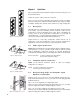
2. 2X 3/8-16 X 2 LG BLACK HEX HEAD ENCLOSURE BRACKET BOLT & LOCK WASHER 2X ENCLOSURE BRACKET P/N 0006118 1/4-20 X 3 LG HEX HEAD RETAINER BOLT & LOCK WASHER Attach the Wall Brackets to structure. You must provide attachment hardware and ensure the attachment method and structure are capable of supporting the intended load. Position the Wall Bracket weld nuts left or right to allow clearance for later insertion of the Retainer Bolt. 3.
Chapter 4 4.1 Description System Overview DSA Series loudspeakers are variable directivity, self-powered line arrays. Each loudspeaker’s vertical beamwidth is determined by the settings of an internal DSP (digital signal processor) and power amplifier for each transducer. This provides complete, on-site control over the range of possible vertical beamwidth patterns. EAW’s Windows-based DSAPilot is used to set the coverage required for each loudspeaker or loudspeaker cluster.
DSA250 EIA-485 AUDIO A INPUT DSP AUDIO B INPUT DSP DSP AMP DSP AMP DSP AMP DSP AMP DSP AMP DSP AMP DSP AMP DSP AMP DSP AMP DSP AMP DSP AMP DSP AMP DSP AMP DSP AMP DSP AMP DSP AMP INPUT DSP AUDIO B INPUT DSP DSP AMP DSP AMP DSP AMP DSP AMP DSP AMP DSP AMP DSP AMP DSP AMP Features 4.2.
· Cat-5 Link Cable links adjacent loudspeakers. · Optional CobraNet™ interface for digital distribution of audio and computer control via Ethernet · Provision for back up audio/computer communications using a redundant Ethernet network, when using CobraNet™. 4.2.
4.4 Engineering Design The core acoustical design of the DSA Series dates back to the late 1930s in Harry Olson’s book, “Acoustical Engineering”. He showed that, by using different signal delays on the input to each transducer in a simple line array, the array’s main output lobe could be effectively “steered”. While this concept has certainly been used before, the design of the DSA Series goes far beyond this simple concept.
The required signal processing, accomplished by DSP (digital signal processing), involves parametric equalization, signal delay, frequency filtering, gain, and limiting. These parameters are individually adjusted by the DSAPilot for each transducer in each loudspeaker. The available DSP resources provide a broad range of possible coverage patterns and SPL control over distance as well as the “voicing” required for exceptional music reproduction.
additional benefits in reduced installation costs and operation. The flexibility of the DSAPilot to automatically optimize the acoustical performance for multiple DSA Series loudspeakers in a single larger space further enhances their advantage over traditional solutions. 4.8 Designing DSA Systems DSA loudspeakers can be used individually, in multiples, or in various cluster configurations to satisfy a wide range of design requirements.
5.1.2 AUDIO SIGNAL CONNECTION CobraNet™: Skip to Section 5.2 if using CobraNet™ for distribution of the audio and control signals. Audio A or Audio B: 2-conductor twisted pair, shielded, audio cable connected to supplied 3-pin Phoenix Contact Terminal Plug and to the line level audio signal source. Nominal level: 0 dBu / 0.775 V rms. Recommended Conductor Gauge: 24 AWG to 18 AWG / 0.2 mm to 1 mm Audio A and Audio B: As above but 4-conductor twisted pairs 5.1.3 AUDIO – AUDIO + SHIELD Figure 5.1.
5.1.5 AUDIO A EIA-485 DAISY CHAINING COMPUTER AND AUDIO SIGNALS BET WEEN CLUSTERS Any distance (within EIA-485 limitations) between clusters: 2-conductor shielded cable AUDIO B Audio A, Audio B, and EIA-485 Connect in parallel to the incoming signal cables on one loudspeaker in the first cluster and connect to the same signal ports on one loudspeaker in the next cluster. Use the supplied 3-pin Phoenix Contact terminal plugs. Recommended Conductor Gauge: 24 AWG to 18 AWG / 0.2 mm to 1 mm Figure 5.1.
5.2.3 A D D I T I O N A L E Q U I P M E N T YO U M U S T S U P P LY F O R C O B R A N E T ™ : · Loudspeaker interface: EAW CM-1 CobraNet™ Interface Card (P/N 0005987) for each DSA Series loudspeaker · Audio/Computer interface: Converts signals to CobraNet™ protocol · Ethernet switch or hub: For networking multiple loudspeakers over Ethernet 5.2.4 LINE LEVEL AUDIO SOURCE(S) CABLING: A CAT-5 or better cable with RJ-45-compatible connectors is required for each loudspeaker.
5.3 AC Mains Power Connection This section details the requirements for the AC mains which is the AC power connection required by each DSA loudspeaker. 5.3.1 A C M A I N S S U P P LY CAUTION: Read all cautionary notes concerning electrical power in Chapter 1. Each DSA Series loudspeaker is rated for a particular nominal AC Mains voltage: 115 V or 230 V.
The LED should then go off. See Section 6.1.2 for other LED indications. If it is desired to completely power off (de-energize) the loudspeaker, a conveniently located AC mains disconnect must be supplied or the power cable must be unplugged from the loudspeaker or the AC mains supply. The PowerCon connector is a locking connecter. To lock, twist 1/4 turn clockwise after fully inserting into the jack. It is recommended the connection be made at the loudspeaker before connection to the AC mains supply.
5.5 Physical Installation This section details the physical requirements and methods for installing the loudspeaker. Specific mounting procedures detailed herein may require some variation depending on the particular situation. However, the basic methodology is the same in all cases. Basic installation tasks include: Installing the Enclosure and Wall Brackets Mounting the loudspeaker 5.5.
orientation and, when multiple loudspeakers are used, the correct location of each. For the DSA250, the Power End is the end with the HF subsystem and Signal End is the end with the LF subsystem. 5.5.3 M U LT I P L E LO U D S P E A K E R S A N D C LU S T E R C O N F I G U R AT I O N S CAUTION: Only clusters included in DSAPilot may be used. Any other configurations will result in poor to unusable performance. Several cluster configurations are shown in Figure 5.5.3.
5.5.4 WALL I N S TA L L AT I O N O P T I O N S Normal Method: This method is for installing DSA loudspeakers flush-mounted to a vertical wall surface using the supplied brackets. The installation instructions herein apply to this installation method. DSA SUPPLIED WALL BRACKETS Figure 5.5.4a Wall Mounted USER-SUPPLIED SUSPENSION HARDWARE Optional Normal Method: This method is for suspending DSA loudspeakers. The optional DSA Fly-Bar Kit is required for suspension.
GOOD BAD Figure 5.5.5b Horizontal Rotation Over / Under Enclosures 5.5.6 BAD GOOD Figure 5.5.5c Horizontal Rotation Side-by-Side Enclosures MOUNTING HEIGHT The acoustical reference point for the DSAPilot is the geometric center of the cluster, which is halfway between the top of the top enclosure to the bottom of the bottom enclosure. That means for a steering angle of 0 degrees “on-axis” is the physical center of the cluster. The elevation entered into DSAPilot refers to this point.
8.5 in MIN IMUM TO CEILING Critical Dimensions: 1. Spacing between the Wall Brackets for a single loudspeaker must be within 0.1 in / 3 mm of the dimensions in Figure 5.5.7a. In order to lift a loudspeaker onto its wall brackets, spacing between the top wall bracket and ceiling, or other overhead obstruction, must be 8.5 inches minimum. NOTE: 8.5 inches allows only 0.25 inches extra clearance. DSA250 38.1 in 968.3 mm DSA230 23.9 in 606.3 mm Figure 5.5.7a Wall Bracket Spacing 2.
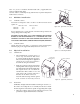
5.5.8 E N C LO S U R E B R A C K E T I N S TA L L AT I O N Insert each supplied Enclosure Bracket into its slot near each end of the enclosure, verifying the proper orientation of the enclosure. Insert a supplied 3/8-16 x 2 in Enclosure Bracket Bolt with its lock washer into each bracket bolt hole in the enclosure. Thread each bolt into the weld nut on its Enclosure Bracket and hand-tighten.
1/4-20 X 3 LG HEX HEAD SCREW & LOCK WASHER 1/4-20 WELD NUT 1. Install at least one of the supplied 1/4-20 X 3 in Retainer Bolt with its lock washer through the side of either the top or bottom Wall/Enclosure Bracket and snugly tighten. The bolt threads into a weld nut on the side of the Wall Bracket. This Retainer Bolt prevents the enclosure from being lifted off the Wall Brackets without first removing the bolt. Note that the Retainer Bolt does not “clamp” or support anything.
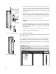
5.6 Initial Set-Up 5.6.1 V E R I F Y LO U D S P E A K E R O R I E N TAT I O N A N D P O S I T I O N LED INDICATOR Using the DSAPilot, and with communications established with the loudspeakers, click on each loudspeaker in DSAPilot. The LED in both the DSAPilot graphic and on the actual loudspeaker will illuminate. Ensure that the physical orientation and position of each loudspeaker corresponds to that shown in the DSAPilot graphic. See the DSAPilot help file for further information.
Chapter 6 Operation The general operation of a DSA loudspeaker is similar to the operation of most loudspeakers. Initial system set-up and overall tuning adjustments detailed in this Chapter must be made using DSAPilot. For details about using DSAPilot functions refer to the DSAPilot Help File.
2. Input Clip: If this indication is enabled, random flashing shows that the audio input signal is clipping the A to D converters at the input. To correct this condition, reduce the input signal level at the source. Because the input gain is after the A to D converters, the DSA input gain adjustment will have no effect on this condition. NOTE: This is likely an unusual condition because the LED will respond only if the input signal levels are greater than +24 dBu.
6.2 Operational Check List To operate a DSA loudspeaker, pre-performances checks and adjustments should be made. In typical permanently installed applications, these checks would normally be one-time, set-up adjustments that may only need to be periodically verified. All of these steps require using DSAPilot. 1. Set the Power Management function as appropriate for your application. 2. Select each cluster in the DSAPilot design and verify the LED indicator illuminates on the corresponding physical cluster.
6.3.3 O P E R AT I O N Operate DSA similarly to any other loudspeaker. This normally involves setting the source levels to achieve the desired output as well as applying external equalization or other signal processing to achieve certain desired results. DSA’s internal signal processing, set using DSAPilot, should not be used for in performance adjustments. 6.4 Operational ‘DOS’ and ‘DONTS’ 6.4.
Chapter 7 - Maintenance and Service This chapter provides information about warranty coverage and service. 7.1 Wa r r a n t y See the supplied warranty card for warranty details. 7.2 Service Items There are no field serviceable parts for the DSA250 or DSA230. Service and repair information must be obtained by contacting the EAW Service Department or the service department of the EAW Distributor for your country. See Section 7.3 for contact information. 7.
Chapter 8 - Appendices 8.1 Inspections and Maintenance 8.1.1 PERIODIC PHYSICAL INSPECTIONS Complete and thorough inspections should be done on a routine, periodic basis. The interval between inspections and scope of the inspections will depend on the conditions of use. This interval must not exceed 1 year. All mountings and enclosures should be visually examined for any condition that may affect mounting integrity.
8.2 Tr o u b l e s h o o t i n g This troubleshooting table addresses some common faults. For other difficulties not listed, contact the EAW Service Department. SYMPTOM POSSIBLE CAUSE SOLUTION No HF output Failed internal component Loudspeaker needs service. No HF output from one or more drivers Failed internal component Loudspeaker needs service.
the up/down enclosure orientation is correct for the application. Distorted sound Failed internal component(s) Using the DSAPilot’s Service Mode, check the operation of each amplifier and driver. Distorted sound Excessive levels Using the DSAPilot, monitor the DSA signal path to check for clipping at all monitoring points. Distorted sound Bad input signal Use a substitute amplifier and loudspeaker to check the quality of the input signal to the DSA Series loudspeaker.
8.3 EIA-485 Network EIA-485 network cabling has certain limitations that these notes summarize. Improper set-up of an EIA-485 network can result in faulty or no operation. To use EIA-485 network configurations or cabling schemes not addressed in this manual, consult a qualified network professional. 8.3.1 CABLING NOTES: 1.
8.3.2 T E R M I N AT I O N N O T E S : 1. The DSA Terminate Switch connects a 120 ohm resistor as a load on the EIA-485 cabling. 2. Normally, USB to EIA-485 or RS-232 to EIA-485 converters also have a termination resistor connected as a load on the computer end of the EIA-485 cabling. If optional, this termination should be switched on. Both this termination resistor and the one in the loudspeaker at the far end of the EIA-485 cabling from the computer are required to ensure proper network operation. 3.
Chapter 9 - Mechanical Drawings 9.1 DSA230 INPUT PANEL SIGNAL END CABINET WEIGHT= 62 LBS 9.34 9.32 11.24 FROM WALL LED 2X 14° 2X 20° 8.26 23.89 36.51 (4.
9.2 DSA250 INPUT PANEL SIGNAL END 9.34 CABINET WEIGHT = 84 LBS 9.32 11.24 FROM WALL LED 2X 20° 2X 14° 8.26 50.80 38.17 (4.
9.3 WA L L B R A C K E T 4.22 in (107.3 mm ) 3.47 in (88.3 mm) 0.38 in (9.7 mm) 0.38 in (9.7 mm) 0.62 in (15.8 mm) 4.00 in (101.5 mm ) 2.76 in (70.0 mm) 4X Ø 0.38 in (9.65 mm) 0.62 in (15.8 mm) FIGURE 9.3 WALL BRACKET (FULL SCALE) 3.0 inch standard (76.2 mm) Verify this dimension before using this template. When printing this PDF template make sure to deselect "Fit to page" option. See Section 5.5.
O ne Main Street, Whitinsville, MA 01588 508-234-6158 FA X 508-234-8251 P a r t N o .