
Installation Manual


Appendix C
64 H-Max Series Variable Frequency Drive MN04008005E—May 2017 www.eaton.com
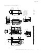
Figure 51. FS9 Dimension Drawing Flange Mount
A/B = 1.18 (30.0)
D = 7.87
(200.0)
A/B = 1.18 (30.0)
Minimum dimensions
A = Air gap around drive
B = Space between two drives
or drive and e.g. cabinet
C = Free space above drive
D = Free space below drive
For class IP54 dim A and B = 0
C = 13.78
(350.0)
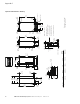
Frame size V
oltage HP (VT) kW Amps Lbs
(kg)
W eight
230 Vac 100–125 HP 75–90 261–310 238.1 (108)
460 Vac 200–250 HP 132–160 261–310 238.1 (108)
9
14.63
(371.6)
0.49
(12.5)
3.54
(90.0)
6.89 (175.0)
19.88 (505.0)
13.98
(355.0)
10.30
(261.5)
1.63
(41.5)
41.34
(1050.0)
4.01
(101.8)
15.65
(397.5)
2.84
(72.0)
3.54
(90.0)
6.89
(175.0)
6.89
(175.0)
0.41
(10.5)
2.54
(64.5)
11.81
(300.0)
11.81
(300.0)
2.84
(72.2)
5.37
(136.4)
40.51
(1029.0)
11.81
(300.0)
6.02
(153.0)
33.09
(840.5)
2.22
(56.5)
4.27
(108.5)
11.50
(292.0)
3.54
(90.0)
1.59
(40.5)
15.75
(400.0)
2.56
(65.0)
18.90
(480.0)
20.87
(530.0)
0.98
(25.0)
6.04
(153.5)
3.21
(81.5)
33.68
(855.5)
39.76
(1010.0)
2.19
(55.5)
0.79
(20.0)
6.04
(153.5)
ø0.87
(22.0)
5.12
(130.0)
3.21
(81.5)
ø0.87
(22.0)
See Detail B
0.32
(8.0)
0.26
(6.5)
0.26
(6.5)
0.32
(8.0)
Detail B
Scale 1:5
ø0.35
(9.0)
ø0.35
(9.0)
ø0.35
(9.0)
3.35
(85.0)
ø0.79
(20.0)
31.89
(810.0)
2.87
(73.0)
2.17 (55.0)
12.01 (305.0)
14.17 (360.0)
ø0.39m (10.0)
ø0.39m (10.0)
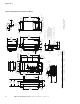
Dimensions = Inches (mm)
FS9 OPEN Chassis/IP00
ø1.00
(25.3)
1.65
(42.0)
1.65
(42.0)
1.65
(42.0)
12.52
(318.0)
4.31
(109.5)
8.25
(209.5)