
Installation Manual


Appendix C
58 H-Max Series Variable Frequency Drive MN04008005E—May 2017 www.eaton.com
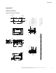
Figure 45. FS7 Dimension Drawing Flange Mount
A/B = 1.18 (30.0)
Dimensions = Inches (mm)
D = 3.94
(100.0)
A/B = 1.18 (30.0)
Minimum dimensions
A = Air gap around drive
B = Space between two drives
or drive and e.g. cabinet
C = Free space above drive
D = Free space below drive
For class IP54 dim A and B = 0
C = 9.84
(250.0)
Frame size V
oltage HP (VT) kW Amps Lbs
(kg)
W eight
230 Vac 25–40 HP 18.5–30 75–105 82.6 (37.5)
460 Vac 50–75 HP 37–55 72–105 82.6 (37.5)
7
0.79
(20.0)
0.28
(7.0)
25.98
(660.0)
0.49
(12.5)
4.33
(110.0)
6.16
(156.5)
10.49
(266.5)
Metric/UL
1.77
(45.0)
3.47
(88.0)
ø1.00
(25.3)
ø1.98
(50.3)
2.52
(64.0)
2.72
(69.0)
2.72
(69.0)
6.28
(159.5)
1.95
(49.5)
2.24
(56.8)
1.77
(45.0)
24.65
(626.0)
9.06
(230.0)
2.84
(72.1)
26.77
(680.0)
23.33
(592.5)
15.55
(395.0)
1.16
(29.5)
7.78
(197.5)
17.39
(441.7)
10.04
(255.0)
0.22
(5.5)
10.47
(266.0)
4.01
(101.9)
See Detail A
0.22
(5.5)
0.30
(7.5)
2.56
(65.0)
7.48
(190.0)
25.39
(645.0)
0.25
(6.3)
7.48
(190.0)
ø0.34
(8.5)
ø0.34
(8.5)
ø0.63
(16.0)
24.80
(630.0)
0.59
(15.0)
0.39
(10.0)
2.17
(55.0)
0.59
(15.0)
ø0.34
(8.5)
ø0.79
(20.0)
ø0.79
(20.0)
Detail A
Scale 1:2
0.43
(11.0)