
Installation Manual


Appendix C
54 H-Max Series Variable Frequency Drive MN04008005E—May 2017 www.eaton.com
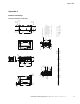
Figure 41. FS5 Dimension Drawing Flange Mount
8.72
(221.5)
6.34
(161.0)
0.51
(13.0)
0.91
(23.0)
1.14
(29.0)
0.32
(8.00)
ø0.26
(6.7)
ø0.26
(6.7)
5.71
(1
45.0)
0.32
(8.0)
5.71
(145.0)
2.84
(72.2)
0.28
(7.0)
1
6.54
(420.1)
0.69
(17.5)
4.01
(101.9)
17.09
(434.1)
10.30
(261.5)
4.78
(121.5)
3.94
(100.0)
15.04
(382.0)
0.55
(14.0)
3.35
(85.0)
4.53
(115.0)
15.98
(406.0)
ø0.28
(7
.0)
ø0.28
(7.0)
ø0.55
(1
4.0)
1.69
(43.0)
1
.69
(43.0)
1
.48
(37.5)
1.48
(37.5)
1.48
(37.5)
1.48
(37.5)
1.48
(37.5)
1.48
(37.5)
5.26
(133.7)
5.26
(133.7)
1.33
(33.7)
1.33
(33.7)
0.14
(3.5)
1.46 (37.0)
1.46 (37.0)
1.46 (37.0)
1.46 (37.0)
2x
ø1.30 (33.0)
4x
ø1.00 (25.3)
3x
ø0.89 (22.5)
3x
ø1.11 (28.3)
1
.71 (43.5)
1.71 (43.5)
IP 21/54 Metric
IP 21/54 UL
A/B = 0.79
(20.0)
Dimensions = Inches (mm)
2 FS4 NEMA
Type 1/IP24
NEMA
T
ype 12/IP54
D = 4.72
(120.0)
A/B = 0.79 (20.0)
Minimum dimensions
A = Air gap around drive
B = Space between two drives
or drive and e.g. cabinet
C = Free space above drive
D = Free space below drive
For class IP54 dim A and B = 0
C = 2.36
(60.0)
Frame size Voltage HP (VT) kW
Amps Lbs (kg)
Weight
230 V
ac 5–10 HP
4–7.5 18–31 22 (10)
460 Vac 10–20 HP 7.5–15 16–31 22 (10)
5
0.95
(24.0)
0.19
(4.8)
4.53
(115.0)
3.35
(85.0)