
Installation Manual


Appendix A
46 H-Max Series Variable Frequency Drive MN04008005E—May 2017 www.eaton.com
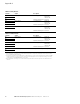
Table 20. Relay Board 1
1
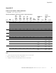
Table 21. Relay Board 2
3
Notes
1
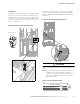
Relay board with two change-over contact (SPDT) relays and one relay with normally-open (NO or SPST) contact.
5.5 mm isolation between channels.
2
If 230 Vac is used as control voltage from the output relays, the control circuitry must be powered with a separate
isolation transformer to limit short circuit current and overvoltage spikes. This is to prevent welding on the relay
contacts. Refer to standard EN60204-1, section 7.2.9.
3
Relay board with two change-over contact (SPDT) relays and a PTC thermistor input. 5.5 mm isolation between
channels.
Terminal Signal Description
21 Relay output 1
2
Switching capacity 24 Vdc/8A
250 Vac/8A
125 Vdc/0.4A
Minimum switching load 5V/10 mA
22
23
24 Relay output 2
2
Switching capacity 24 Vdc/8A
250 Vac/8A
125 Vdc/0.4A
Minimum switching load 5V/10 mA
25
26
32 Relay output 3
2
Switching capacity 24 Vdc/8A
250 Vac/8A
125 Vdc/0.4A
Minimum switching load 5V/10 mA
33
Terminal Signal Description
21 Relay output 1
2
Switching capacity 24 Vdc/8A
250 Vac/8A
125 Vdc/0.4A
Minimum switching load 5V/10 mA
22
23
24 Relay output 2
2
Switching capacity 24 Vdc/8A
250 Vac/8A
125 Vdc/0.4A
Minimum switching load 5V/10 mA
25
26
28 Thermistor input Rtrip = 4.7 kohms (PTC), measuring voltage 3.5V
29