
Installation Manual


Installation Requirements
32 H-Max Series Variable Frequency Drive MN04008005E—May 2017 www.eaton.com
Control Wiring
●
All control I/O wiring must be segregated from line (mains)
and motor cabling
●
Control wiring shall be shielded twisted pairs. To meet
EMC levels required by ENG1800-3 (2004).
Control wiring must be Type 4 cable
●
Run 120 Vac and +24 Vdc control I/O in separate conduit
●
Control I/O terminals must be tightened to 4.5 lb (0.5 Nm)
LED Functionality
The status LED of the drive shows the status of the drive.
The status LED is located in the control panel, below the
keypad, and it can show 5 different statuses.
Table 15. LED Status
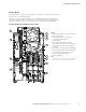
DIP Switch Functionality
You can make 2 selections with the DIP switches for
specified terminals. The switches have 2 positions: up and
down. You can see the location of the DIP switches and the
possible selections below.
Figure 23. DIP Switch Functionality
A. The voltage signal (U), 0–10 V input
B. The current signal (I), 0–20 mA input
C. OFF
D. ON
E. The RS-485 bus termination
Table 16. DIP Switch
Color of the LED Light Status of the Drive
Green—blinking slowly Ready
Green—steady Run
Red Fault
Orange Alarm
Green—blinking fast Downloading software
DIP Switch Default Position
AI1 I
AI2 I
AO1 I
RS-485 bus termination OFF
A B
A
B
C
D
E
AI2
U
I
AI1
U
I
RS-485
OFF
ON
AO1
U
I