
Installation Manual


Installation Requirements
H-Max Series Variable Frequency Drive MN04008005E—May 2017 www.eaton.com 31
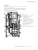
Control Board
The main H-Max Series VFD consists of a main control board, control I/O connections block
and two slots for extra option boards.
This main control board launched March 2017. Serial Numbers after C171201265 were
manufactured with this main control board. All units manufactured prior shipped with an
old style control board. The new main control board contains backward compatibility.
Figure 22. H-Max Series Variable Frequency Drive
L
I
K
H
G
F
J
E
D
A
B
C
Legend
A. The control terminals for the standard I/O connections
B. The Ethernet connection
C. The relay board terminals for 3 relay outputs
or 2 relay outputs and a thermistor
D. The option boards
1
E. A DIP switch for the RS-485 bus termination
F. A DIP switch for the signal selection of analog output
G. A DIP switch for the isolation of the digital inputs
from ground
H. A DIP switch for the signal selection of Analog Input 2
I. A DIP switch for the signal selection of Analog Input 1
J. The status indicator of the Ethernet connection
K. A fan (only in IP54 of FR4 and of FR5)
L. The battery for the RTC
Note
1
Expansion slots D and E will accept option boards. Slot C is
inactive and will not function with any option board.