
Installation Manual


Installation Requirements
22 H-Max Series Variable Frequency Drive MN04008005E—May 2017 www.eaton.com
Mounting dimensions:
●
Refer to Page 23 for drive dimensions
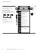
Figure 17. Mounting Space
Table 8. Space Requirements for Mounting the H-Max Series VFD and Airflow
Notes
1
kW ratings are at 400V/50 Hz.
2
Minimum clearances A and B for drives with NEMA 12 (IP54) enclosure is 0 mm (in).
Frame
Size
Line
Voltage hp (VT) kW
1
Amperes
A
2
in (mm)
B
2
in (mm)
C
in (mm)
D
in (mm)
Cooling Air
Required
FS4 230V 0.75–4 0.55–3.0 3.7–12.5 0.8 (20) 0.8 (20) 3.9 (100) 3.0 (50) 27 CFM
45 m
3
/h
480V 1.5–7.5 1.1–5.5 3.4–12
FS5 230V 5–10 4–7.5 18–31 0.8 (20) 0.8 (20) 4.7 (120) 2.4 (60) 45 CFM
75 m
3
/h
480V 10–20 7.5–15 16–31
600V 3–10 — 3.9–11
FS6 230V 15–20 11–15 48–62 0.8 (20) 0.8 (20) 6.3 (160) 3.1 (80) 112 CFM
190 m
3
/h
480V 25–40 18.5–30 38–61
600V 15–30 — 18–34
FS7 230V 25–40 18.5–30 75–105 0.8 (20) 0.8 (20) 9.8 (250) 3.9 (100) 109 CFM
185 m
3
/h
480V 50–75 37–55 72–105
600V 40–60 — 41–62
FS8 230V 50–75 37–55 140–205 0.8 (20) 0.8 (20) 11.9 (300) 6.0 (150) 209 CFM
335 m
3
/h
480V 100–150 75–110 140–205
600V 75–125 — 80–125
FS9 230V 100–125 75–90 261–310 0.8 (20) 0.8 (20) 13.8 (350) 7.9 (200) 366 CFM
621 m
3
/h
480V 200–250 132–160 261–310
600V 150–200 — 144–208
D
B
C
B
AA
2