
Installation Manual


System Overview
10 H-Max Series Variable Frequency Drive MN04008005E—May 2017 www.eaton.com
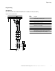
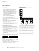
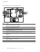
Figure 11. Block Diagram, Elements of H-Max Frequency Inverters
Item
Number Description
1 Supply L1, L2/N, L3, PE, input supply voltage U
LN
=U
e
at 50/60 Hz:
HMX32: 200V class, three-phase input connection (3 AC 230V/240V)
HMX34: 400V class, three-phase input connection (3 AC 400V/480V)
HMX35: 575V class, three-phase input connection (3 AC 575V/600V)
2 Internal interference suppression filter, category C2 to IEC/EN 61800-3
EMC-connection of internal interference suppression filter to PE
3 Rectifier bridge, converts the AC voltage of the electrical network into DC voltage
4 DC link with charging resistor, capacitor and switching mode power supply unit
(SMPS = Switching Mode Power Supply):
DC link voltage U
DC
with three-phase input connection (3 AC): U
DC
=1.41xU
LN
5 Inverter. The IGBT based inverter converts the DC voltage of the DC link (U
DC
) into a three-phase AC voltage (U
2
) with variable amplitude and
frequency (f
2
). Sinusoidal pulse width modulation (PWM) with V/f control can be switched to speed control with slip compensation
6 Motor connection U/T1, V/T2, W/T3 with output voltage U
2
(0–100% U
e
) and output frequency f
2
(0–320 Hz) output current (I
2
):
HMX32: 3.7–310A
HMX34: 3.4–310A
HMX35: 3.9–208A
100% at an ambient temperature of 104°F (40°C) with an overload capacity of 110% for 60s every 600s and a starting current of 200% for 2s every 20s
7 Keypad with control buttons, graphic display, control voltage, control signal terminals, microswitches, and interface for the PC interface
module (option)
8 Three-phase asynchronous motor, variable speed control of three-phase asynchronous motor for assigned motor shaft power values (P
2
):
HMX32: 0.55–90 kW (230V, 50 Hz) or 0.75–125 hp (230V, 60 Hz)
HMX34: 1.1–160 kW (400V, 50 Hz) or 1.5–250 hp (460V, 60 Hz)
HMX35: 3–200 hp (600V, 60 Hz)
9 DC link—chokes, to minimize current harmonics
+
R+
EMC
L1
L2
L3
PE
R–
M
3 ~
U/T1
V/T2
W/T3
PE