
Installation Manual


Power Wiring
14 9000X AF Drives MN04001004E—May 2011 www.eaton.com
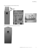
9. Attach the wiring plate with the screws provided.
Ensure that no wires are trapped between the frame and
the wiring plate.
10. Insert the rubber grommets supplied into the wiring
plate holes that have not been used, as illustrated in the
figure to the right.
Cable Protection Plate
Standard Wiring Diagrams and Terminal Locations
The following wiring diagrams show the line and motor connections of the frequency converter.
Principle Wiring Diagram of SVX9000/SPX9000 Power Unit, FR4 to FR5 and FR6
Note: When using a single-phase supply, for units rated for such, connect the input power to
terminals L1 and L2. Consult Eaton for more information.
U
R
–
V
W
L1
See
N
ote
L2
L
3
L1
L2
L
3
D
C
–
DC+
/
R+
BR
O
p
tio
n
M
3
~
Power
Board
Co
n
t
r
ol
B
oa
r
d
230V 3
/4
–15 hp
4
80
V
1
–30 hp
5
7
5
V
2
–25 hp
N
ote:
Inte
g
rated Brake
Cho
pp
er Circuit No
t
In
c
l
uded
o
n
5
7
5
V
u
ni
ts.