
Installation Manual


Power Wiring
9000X AF Drives MN04001004E—May 2011 www.eaton.com 13
Cable Stripping Lengths for Power and Motor Cables
Power and Motor Cable Stripping Lengths
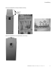
2. Locate the plastic bag containing the wiring plate.
Wiring Plate
3. If conduit is being used, attach the wiring plate to the
drive then conduit.
4. Pass the motor and input power wires/cables through
the holes of the wiring plate.
5. Connect the input power and motor and control wires to
their respective terminals according to the wiring
diagrams in the section marked “Standard Wiring
Diagrams and Terminal Locations” on Page 14.
6. If an optional external brake resistor is used, connect its
cable to the appropriate terminals. See “Standard Wiring
Diagrams and Terminal Locations” on Page 14.
7. If shielded cable is used, connect the shields of the input
line power cable and the motor cable to the ground
terminals of the SVX9000/SPX9000 drive, the motor,
and the line power supply.
Ground Terminal Locations
8. If shielded cable is not used, check the connection of
the ground cable to the motor, the SVX9000/SPX9000
drive, and the input line power terminals marked with
.
Product
Frame
Size
Power Wiring in Inches (mm) Motor Wiring in Inches (mm)
hp Voltage A1 B1 C1 D1 A2 B2 C2 D2
3/4–3 230V FR4 0.59 (15) 1.38 (35) 0.39 (10) 0.79 (20) 0.28 (7) 1.97 (50) 0.28 (7) 1.38 (35)
1–5 480V
5–7-1/2 230V FR5 0.79 (20) 1.57 (40) 0.39 (10) 1.18 (30) 0.79 (20) 2.36 (60) 0.39 (10) 1.57 (40)
7-1/2–15 480V
10–15 230V FR6 0.79 (20) 3.54 (90) 0.59 (15) 2.36 (60) 0.79 (20) 3.54 (90) 0.59 (15) 2.36 (60)
20–30 480V
2–25 575V
20–30 230V FR7 0.98 (25) 4.72 (120) 0.98 (25) 4.72 (120) 0.98 (25) 4.72 (120) 0.98 (25) 4.72 (120)
40–60 480V
30–40 575V
75–125 480V FR8 1.10 (28) 9.45 (240) 1.10 (28) 9.45 (240) 1.10 (28) 9.45 (240) 1.10 (28) 9.45 (240)
50–75 575V
150–200 480V FR9 1.10 (28) 11.61 (295) 1.10 (28) 11.61 (295) 1.10 (28) 11.61 (295) 1.10 (28) 11.61 (295)
100–300 575V