
Firmware Manual


9000X AF Drives
6-16 For more information visit: www.eaton.com
MN04004001E
August 2010
Multi-Purpose Control Application
Table 6-16: Digital Output Signals — G1.3.3 (Continued)
CAUTION
Be ABSOLUTELY sure not to connect two functions to one and
same output in order to avoid function overruns and to ensure
flawless operation.
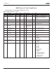
Limit Settings (Control Keypad: Menu M1
➔
G1.3.4)
Table 6-17: Limit Settings — G1.3.4
Code Parameter Min. Max Unit Default ID Note
P1.3.3.27
Fieldbus input data 4 DigOUT:0.1 DigOUT:E.10 DigOUT:0.1 169 FB CW B14
P1.3.3.28
Fieldbus input data 5 DigOUT:0.1 DigOUT:E.10 DigOUT:0.1 170 FB CW B15
Code Parameter Min. Max. Unit Default Cust ID Note
P1.3.4.1 Output frequency
limit 1 supervision
0 3 0 315 0 = No limit
1 = Low limit supervision
2 = High limit supervision
3 = Brake-on control
P1.3.4.2 Output frequency
limit 1; Supervised
value
0.00 Par. 1.1.2 Hz 0.00 316
P1.3.4.3 Output frequency
limit 2 supervision
0 4 0 346 0 = No limit
1 = Low limit supervision
2 = High limit supervision
3 = Brake-off control
4 = Brake on/off-control
P1.3.4.4 Output frequency
limit 2; Supervised
value
0.00 Par. 1.1.2 Hz 0.00 347
P1.3.4.5 Torque limit
supervision
0 3 0 348 0 = Not used
1 = Low limit supervision
2 = High limit supervision
3 = Brake-off control
P1.3.4.6 Torque limit
supervision value
-1000.0 1000.0 % 100.0 349
P1.3.4.7 Reference limit
supervision
0 2 0 350 0 = Not used
1 = Low limit
2 = High limit
P1.3.4.8 Reference limit
supervision value
0.00 Par. 1.1.2 % 0.00 351
P1.3.4.9 External brake-off
delay
0.0 100.0 s 0.5 352
P1.3.4.10 External brake-on
delay
0.0 100.0 s 1.5 353
P1.3.4.11 FC temperature
supervision
0 2 0 354 0 = Not used
1 = Low limit
2 = High limit
P1.3.4.12 FC temperature
supervised value
-10 75 ∞C 0 355