
Firmware Manual


9000X AF Drives
6-10 For more information visit: www.eaton.com
MN04004001E
August 2010
Multi-Purpose Control Application
Analog Input 1 (Control Keypad: Menu M1
➔
G1.2.2)
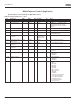
Table 6-8: Analog Input 1 Parameters — G1.2.2
Remember to place jumpers of block X2 accordingly. See 9000X AF Drives User Manual, Chapter 4.
Code Parameter Min. Max. Unit Default ID Note
P1.2.2.1
AI1 signal selection 0 A.1 377 TTF programming.
See chapter 6.3
P1.2.2.2 AI1 filter time 0.00 10.00 s 0.10 324 0 = No filtering
P1.2.2.3 AI1 signal range 0 3 0 320 0 = 0–100%
1 = 4mA/20%–100%
2 = -10V...+10V
3 = Custom range
P1.2.2.4 AI1 custom minimum
setting
-160.00 160.00 % 0.00 321
P1.2.2.5 AI1 custom maximum
setting
-160.00 160.00 % 100.00 322
P1.2.2.6 AI1 reference scaling.
minimum value
0.00 320.00 Hz 0.00 303 Selects the frequency that
corresponds to the min.
reference signal
P1.2.2.7 AI1 reference scaling.
maximum value
0.00 320.00 Hz 0.00 304
P1.2.2.8 AI1 joystick hysteresis 0.00 20.00 % 0.00 384
P1.2.2.9 AI1 sleep limit 0.00 100.00 % 0.00 385
P1.2.2.10 AI1 sleep delay 0.00 320.00 s 0.00 386
P1.2.2.11 AI1 joystick offset -50.00 50.00 % 0.00 165