
Firmware Manual


9000X AF Drives
6-4 For more information visit: www.eaton.com
MN04004001E
August 2010
Multi-Purpose Control Application
Defining a Terminal for a Certain Function with 9000X Drive Programming Tool
If you use the 9000X Drive Programming Tool for parametrizing you will have to establish the
connection between the function and input/output in the same way as with the control panel.
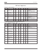
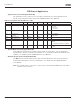
Just pick the address code from the drop-down menu in the Value column (see Figure 6-3).
Figure 6-3: Screenshot of 9000X Drive Programming Tool; Entering the Address Code
CAUTION
Be ABSOLUTELY sure not to connect two functions to one and
same output in order to avoid function overruns and to ensure
flawless operation.
Notice
The inputs, unlike the outputs, cannot be changed in RUN state.
Defining Unused Inputs/Outputs
All unused inputs and outputs must be given the board slot value 0 and the value 1 also for
the terminal number. The value 0.0 is also the default value for most of the functions.
However. if you want to use the values of a digital input signal for e.g. testing purposes only.
you can set the board slot value to 0 and the terminal number to any number between 2…10
to place the input to a TRUE state. In other words, the value 1 corresponds to “open contact”
and values 2 to 10 to closed contact.
In case of analog inputs, giving the value 1 for the terminal number corresponds to 0%, value
2 corresponds to 20% and any value between 3 and 10 corresponds to 100%.