
Firmware Manual


9000X AF Drives
6-2 For more information visit: www.eaton.com
MN04004001E
August 2010
Multi-Purpose Control Application
Control I/O
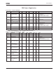
Table 6-1: Multi-Purpose Control Application Default I/O Configuration and
Connection Example
Note: For more information on jumper selections, see the 9000X AF Drives User
Manual, Chapter 4.
Terminal Signal Description
OPTA1
1 +10V
ref
Reference output Voltage for potentiometer, etc.
2 AI1+ Analog input, voltage range
0 – 10V DC
Voltage input frequency reference
3 AI1- I/O Ground Ground for reference and controls
4 AI2+ Analog input, current range
0 – 20 mA
Current input frequency reference
5 AI2-
6 +24V Control voltage output Voltage for switches, etc. max 0.1A
7 GND I/O ground Ground for reference and controls
8 DIN1 Start forward
(programmable)
Contact closed = start forward
9 DIN2 Start reverse
(programmable)
Contact closed = start reverse
10 DIN3 Fault reset (programmable) Contact closed = fault reset
11 CMA Common for DIN1 – DIN3 Connect to GND or +24V
12 +24V Control voltage output Voltage for switches (see terminal 6)
13 GND I/O ground Ground for reference and controls
14 DIN4 Jog speed selection
(programmable)
Contact closed = jog speed active
15 DIN5 External fault
(programmable)
Contact open = no fault
Contact closed = fault
16 DIN6 Accel./decel. time select
(programmable)
Contact open = P1.1.3, P1.1.4 in use
Contact closed = P1.4.3, P1.4.4 in use
17 CMB Common for DIN4 – DIN6 Connect to GND or +24V
18 AOA1+ Output frequency
Analog output
Programmable
Range 0 – 20 mA, R
L
, max. 500W
19 AOA1-
20 DOA1 Digital output
READY
Programmable
Open collector, I ≤ 50 mA, V ≤ 48V DC
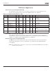
OPTA2
21 RO1 Relay output 1
RUN
Programmable
22 RO1
23 RO1
24 RO2 Relay output 2
FAULT
Programmable
25 RO2
26 RO2
CMB connected to GND
CMA connected to GND
CMB isolated from GND
CMA isolated from GND
CMB and CMA internally connected
together, isolated from GND
= Factory default.
Jumper Block X3: CMA and CMB Grounding
mA
READY
RUN
Reference potentiometer
1 – 10 kW
220V
AC